70
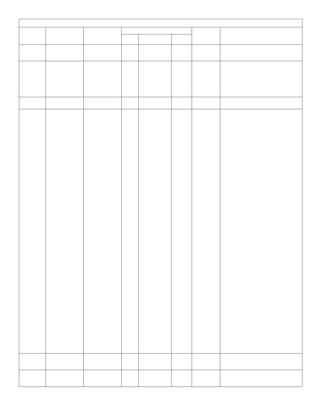
Table 12. CORE Control System Unit Parameters
Control
Parameter
No
Screen Name
Parameter Short
Description
Control Value
Units Description
Min. Default Max.
362
GP DO1 SP
DEGREES
General Purpose
D01 Set Point
Degree
-31 0 132 °F
General Purpose D01 Digital output
control mode set point.
363
GP D01 DB
PERCENT
General Purpose
D01 Dead Band
Percentage
0 0 100 %
General Purpose D01 Digital output
control mode set point.
EXAMPLE: If this Parameter is set
to 10%, then the dead-
band in Fahrenheit would
be (DO Temperature Set
Point * 10 /100).
364
GP D01 TIME
DELAY
General Purpose
D01 Time Delay
1 416 8160 Seconds For delay on or delay off.
365 GP D02 MODE
General Purpose
D02 Mode
0 0 127
Mode
Selection
GP3 Digital Out Control Mode = X + 32*Y
+ 16*Z
Input Sources X:
• 0 = None.
• 1 = Compressor 1 duty cycle.
(Compressor crankcase heater
function)
> On when outdoor air
temperatureis<=Parameter
369 and > = P 371 seconds
have passed with compressor
1 off.
> Off when outdoor air
temperature > Parameter 369
+3°F(xeddead-band)or
compressor 1 is turned on.
• 2 = On when Occupied
• 3 = On when blower on.
• 4 = On when heating demand
• 5 = On when cooling demand
• 6 = On when heating or cooling
demand
• 7 = System RH (use Parameter 368)
• 8 = System IAQ (use Parameter
367)
• 9 = System OAT (use Parameter
369)
• 10 = On based on GP3 Temperature
Sensor 1 (use Parameter 369)
• 11 = On based on GP3 Temperature
Sensor 2 (use Parameter 369)
• 12 = On based on GP3 AI1 (use
Parameter 366)
• 13 = On based on GP3 AI2 (use
Parameter 366)
• 14 = On based on GP3 AO1 (use
Parameter 366)
• 15 = On based on GP3 AO2 (use
Parameter 366)
• Algorithm Y for Input Sources 7-15
(see 507242-01, Prodigy Application
Guide for further details).
366
GP D02 SP
VOLTS
General Purpose
D02 Set Point
Volts
0 0 10 Volts
General Purpose D02 Digital output
control mode set point.
367 GP D02 SP PPM
General Purpose
D02 Set Point
Parts Per Million
21 996 1996 PPM
General Purpose D02 Digital output
control mode set point.