32
whileoperatingtheairconditioner,turnofftheair
conditionerbeforedisconnectingthehose.
• Mountedthevalvestemcapsandtheserviceport.
Usetorquewrenchtotightentheserviceportcaptoa
torqueof18N·m(13.27ft·lbs).
• Alwaysleakcheckafterservicingtherefrigerant
system.
Thereareonelow-pressurecentralizedvalveandonehigh-
pressurecentralizedvalve,itwillbemoretimesavingwhen
vacuum and recycle refrigerant. But refer to the previous
instructionwhenvacuumandrecyclerefrigerant.
13. Electronic Function
13.1. Abbreviation
• T1:Indoorambienttemperature
• T2:Middleindoorheatexchangercoiltemperature
• T3:Outdoorheatexchangerpipetemperature
• T4:Outdoorambienttemperature
• T5:Compressordischargetemperature
13.2. Electric Control Working Environment.
• Inputvoltage:230V.
• Inputpowerfrequency:60Hz.
• Indoorfanstandardworkingamp.:<1A
• Outdoorfanstandardworkingamp.:<1.5A.
• Four-wayvalvestandardamp.:<1A
14. Adding Refrigerant - Single-Zone Systems
Theoutdoorunitisfactory-chargedwithrefrigerant.Calculate
theadditionalrefrigerantrequiredaccordingtothediameter
and the length of the liquid pipe between theoutdoorunit
andindoorunitconnections.
Besuretoaddtheproperamountofadditionalrefrigerant.
Failuretodosomayresultinreducedperformance.
See “Table 4. Line Set Guide” on page 26 for how much
refrigerantneedstobeaddedbasedonpipelength.
NOTE: Interconnecting pipe work between outdoor and
indoor units must be 10 ft. or longer.
NOTE: Do not remove refrigerant for line lengths less
than 25 ft. R-410A is a blended refrigerant. If you
must remove charge, it is necessary to remove
the entire charge and weigh in the new charge.
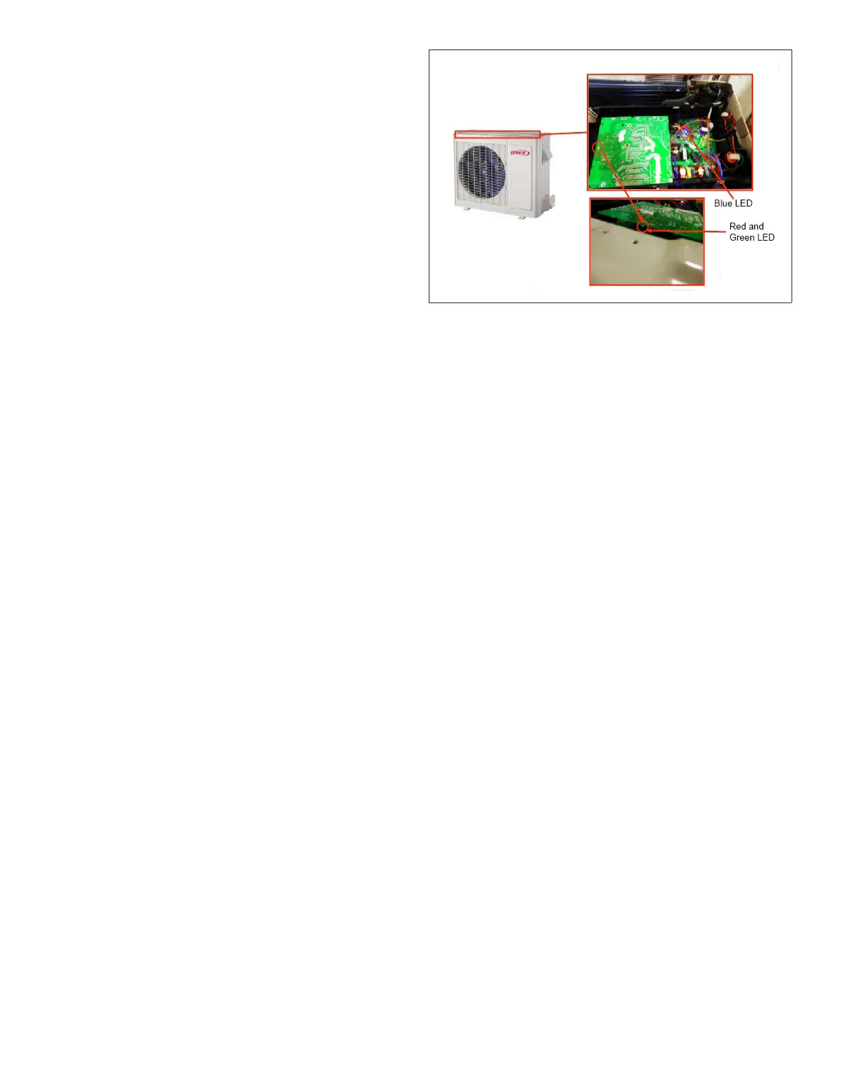
15. Single-Zone Outdoor Unit LED Locations
Single-zoneoutdoor unitsdisplay ashcodesonthemain
board.Themain boardisaccessedthroughthetopofthe
unit.Indoorunitswilldisplaymoredetailederrorcodes.
These outdoor units do not have a SW1 spot check push
button switch.Diagnosticisperformed through a series of
blue,redandgreenLEDs.
NOTE: The control on all single-zone outdoor units is
mounted with all LEDs down and cannot be seen
unless the control is removed.
Figure 24. Typical Location of Outdoor Unit LEDs
 Loading...

