8
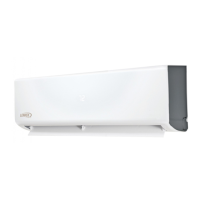
3.3. Terminal Connections
208/230V Outdoor Unit
Terminal Block
From Power
Supply
Terminal Block
208/230V Indoor Unit
Outdoor Unit Indoor Unit
3
2
L1
L2
1
Y/G
1
3
Y/G
Y/G
115VAC Outdoor Unit
Terminal Block
From Power
Supply
Terminal Block
115VAC Indoor Unit
Outdoor Unit Indoor Unit
3
2
L
N
1
Y/G
1
3
Y/G
Y/G
*
*
18 and 24K
unit has
five terminal
sets.
Figure 6. Single Zone Wiring
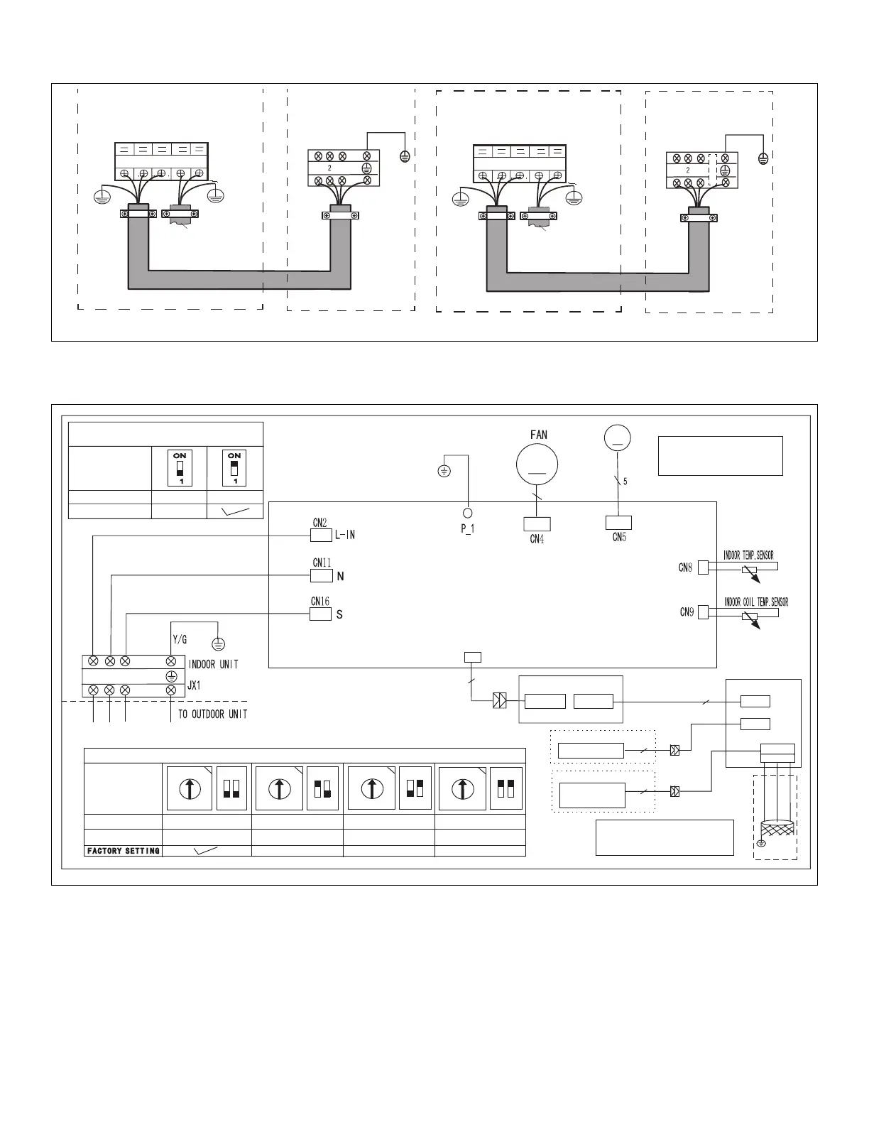
4. Indoor Unit Diagrams
WIRING DIAGRAM (INDOOR UNIT)
SWING MOTOR1
M
YELLOW
RED
M
5
1
2
3
BLACK
CN10A
DI SP LA Y BOARD
8
Wired Controller
OPTIONAL
ADAPTER BOARD
CN3(CN301)
0
8
4
1
2
3
5
6
7
C
9
A
B
D
E
F
1
2
ON
0
8
4
1
2
3
5
6
7
C
9
A
B
D
E
F
1
2
ON
0
8
4
1
2
3
5
6
7
C
9
A
B
D
E
F
1
2
ON
0
8
4
1
2
3
5
6
7
C
9
A
B
D
E
F
1
2
ON
ENC2+S1
0~F
0~F
0~F
0~F
NETADDRESS
CODE
0~15
16~31
32~47
48~63
FOR SETTING NETADDRESS
CN501
CN403
X Y E
To LVM
Comm.Bus
YELLOW
BROWN
RED
5
5
Programmable
Wired Controller
OPTIONAL
4
Note: The programmable wired
controller and LVM use the same
port CN403.
CN2(CN201)
NOTE: COMPONENT IN
DASH LINE IS OPTIONAL
OR FIELD WIRING
CN402
S5
FOR REMOTE ON/OF
FACTORY SETTING
MODE
REMOTE ON/OFF OFFREMOTE ON/OFF ON
Figure 7. 09K, 12K, 18K and 24K Indoor Unit Wiring Diagram (115 and 208/230VAC)
 Loading...

