Page 42
XC17
Table 12. Fan Motor Control Flash and Pause Durations
Flash or Pause State Duration
Flash Flash Three flashes per second
Slow Flash One flash per second
Short Pause Two seconds of OFF time.
Long Pause Five seconds of OFF time.
Table 13. Fan Motor Control (A177) Error/Fault LED Codes
Unit Status Fan Motor Control LED Possible Cause
Mismatched RPM Fast Flash with no pause Internal feedback, PWM does not match target.
CRC Failure Constant ON. Microcontroller CRC failure.
Table 14. One Stage Fan Motor Control RPM Jumper Settings, LED RPM Indicator and P2 DC Voltage Outputs
Model
CFM Profile Pin Select ECM1/Y1
LED Code*
4 3 2 1 RPM (J2) DC Volt
XC17−024 OFF ON ON ON 400 12.7 5
XC17−030 OFF ON ON OFF 450 14.3 6
XC17−036, −042 OFF OFF ON ON 600 19.2 8
XC17−048, −060 OFF OFF OFF ON 675 21.6 9
* LED Code indicates Fan Motor Control LED flash sequence. For example, LED Code 9 indicates 9 slow flashes and pause.
Table 15. Fan Motor Control Unit LED Codes
Unit Status Unit Status Fan Motor Control LED
One Stage Operation Low Stage ECM1/Y1 ONLY One slow flash, then short pause.
RPM Indicator
NOTE There is a long pause between stage
operation and RPM indicator. See tables 1 and 2
for LED RPM indicator.
RPM Indicator
Appropriate number of flashes (see tables
14).
Flash Flash = Three flashes per second.
Slow Flash = One flash per second.
Short Pause = Two seconds of OFF time.
Long Pause = Five seconds of OFF time.
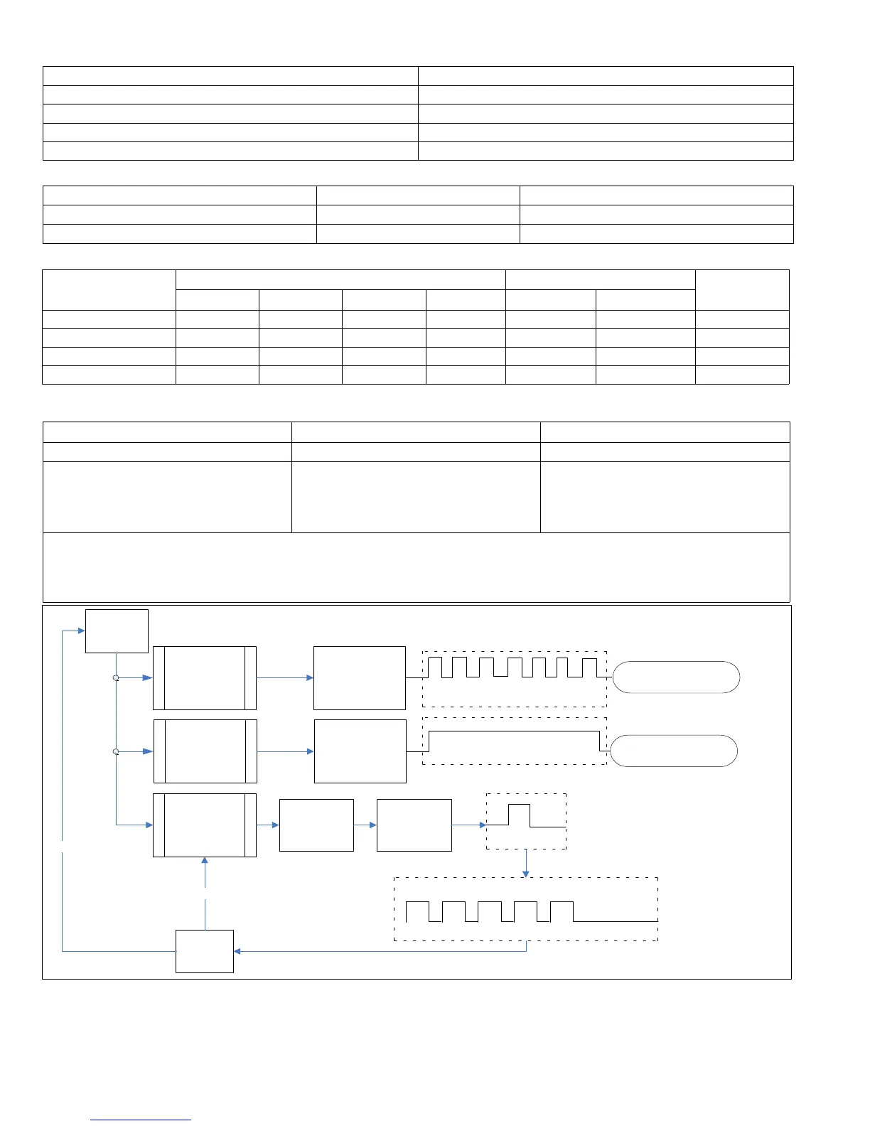
DEMAND
BEGINS
MISMATCHED
RPM
DEFAULT FAN
MOTOR SPEED
USED
LED CONTINUOUS FAST
FLASH
REPLACE FAN MOTOR
CONTROL BOARD
CRC FAILURE
DEFAULT FAN
MOTOR SPEED
USED
LED CONSTANT ON
REPLACE FAN MOTOR
CONTROL BOARD
SINGLE STAGE
OR EDA
OPERATION
ECM1/Y1
ONLY OR
ECM2/Y2
ONLY
STAGE LED INDICATOR: ONE
SLOW FLASH AND ONE
SHORT PAUSE FOR SINGLE
STAGE OR EDA OPERATION
LED RPM INDICATOR:
EXAMPLE: (2−TON
UNIT) – 5 SLOW
FLASHES AND ONE
LONG PAUSE
DEMAND
ENDED
NO
YES
FAN MOTOR
RPM SET PER
JUMPER
SETTINGS
Figure 20. Fan Motor Control One Stage LED Sequence of Operation
 Loading...