EasyManua.ls Logo

Lennox ZGB Series User Manual

Lennox ZGB Series
55 pages
To Next Page IconTo Next Page
Page #1 background imageLoading...
Page #1 background image
Page 1
UNIT INFORMATIONUNIT INFORMATION
Service Literature
WARNING
To prevent serious injury or death:
1- Lock-out/tag-out before performing maintenance.
2- If system power is required (e.g., smoke detector
maintenance), disable power to blower, remove
fan belt where applicable, and ensure all
controllers and thermostats are set to the “OFF”
position before performing maintenance.
3- Always keep hands, hair, clothing, jewelry, tools,
etc., away from moving parts.
Table of Contents
Options / Accessories . . . . . . . . . . . . . . . . . . . . . Page 2

Spec. Gas Heat High Altitude. . . . . . . . . . . . . . . . . . . Page 7
Blower Data . . . . . . . . . . . . . . .. . . . . . . . . . . . . . . . . . .Page 7
Electrical Data . . . . . . . . . . . .. . . . . . . . . . . . . . . . . .Page 21
I Unit Components. . . . . . . . . . .. . . . . . . . . . . . . . . . .Page 25
II Placement and Installation . . . . .. . . . . . . . . . . . . .Page 35
III Start-Up and Installation . . . . . . . . . . .. . . . . . . . .Page 35
IV Charging. . . . . . .. . . . . . . . . . . . . . . . .. . . . . . . . . .Page 37



VIII Diagrams . .. . . . ... . . . . . .. . . . ... . . . . . .. . . . .Page 51
The ZGB packaged gas units are available in standard
󰀩-

        

     



aluminized steel tube heat exchangers.
Information contained in this manual is intended for use

subject to change. Procedures outlined in this manual are
presented as a recommendation only and do not super-
sede or replace local or state codes.



for the proper rigging technique. Stacking brackets can be
removed or left on the unit permanently. If brackets are

replaced.
WARNING
    
    
injury or loss of life. Installation and service must be
performed by a licensed professional HVAC installer or

WARNING
Electric shock hazard. Can cause injury
or death. Before attempting to perform
any service or maintenance, turn the
electrical power to unit OFF at disconnect
switch(es). Unit may have multiple power
supplies.
CAUTION
As with any mechanical equipment, contact with
sharp sheet metal edges can result in personal
injury. Take care while handling this equipment and
wear gloves and protective clothing.
ZGB SERIES
3, 4, 5 and 6 Ton
10.6 to 20.3 kW


ZGB036, 048, 060, 074
Question and Answer IconNeed help?

Do you have a question about the Lennox ZGB Series and is the answer not in the manual?

Lennox ZGB Series Specifications

General IconGeneral
BrandLennox
ModelZGB Series
CategoryAir Conditioner
LanguageEnglish

Summary

Unit Information and Service Literature

General Unit Description

Provides overview of ZGB series, capacities, and heat options.

Safety Warnings and Precautions

Highlights critical safety warnings regarding installation, electrical hazards, and sharp edges.

Optional Accessories

Cooling, Heating, and Blower Options

Lists available accessories for cooling, heating, and blower systems.

Economizers, Air Quality, and Other Options

Details economizers, indoor air quality sensors, roof curbs, and ceiling diffusers.

Product Specifications

General Data and Cooling Performance

Covers nominal tonnage, efficiency, cooling capacity, SEER, and EER.

Gas Heat and Blower Specifications

Details gas heat inputs, outputs, temperature rise, and blower data.

Blower Performance Data

Direct Drive Blower Data (3-5 Ton)

Provides CFM, Watts, RPM for various static pressures for direct drive models.

Belt Drive Blower Data (3-6 Ton)

Lists CFM, RPM, and BHP for belt drive models across different static pressures.

Blower System Configurations

Belt Drive Kit Specifications

Details belt drive kit part numbers, motor HP, and RPM ranges.

Power Exhaust Fan Performance

Lists air volume exhausted based on return air system static pressure.

Airflow Resistance and Throw Data

Accessory Air Resistance

Provides static pressure drops for options like heat exchangers and economizers.

Ceiling Diffuser Performance

Details air resistance and air throw for various ceiling diffuser models.

Electrical Data

Direct Drive Blower Electrical Specs

Lists compressor, fan, and power exhaust electrical ratings for direct drive models.

Belt Drive Blower Electrical Specs

Details electrical data for belt drive models across different voltages and phases.

Unit Components Identification

Parts Arrangement Diagram

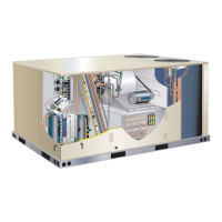
Illustrates the physical layout of major components within the unit.

Control Box Components

Identifies components within the ZGB control box.

Unit Component Details

ESD Precautions and Control Box Components

Covers ESD procedures and lists key control box components and their functions.

Burner Control System

Ignition Control A3 Functions and Status

Explains the functions of the burner control board and LED status indicators.

Unit Operation Principles

Heating Operation and Compressor Safety

Describes heating sequence, compressor operation, and safety precautions.

Cooling System Components and Operation

Details cooling circuit components and operational notes.

Refrigeration System Plumbing

Plumbing Diagram and Components

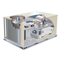
Shows the layout of refrigeration components like evaporator coil, compressor, and condenser coil.

Installation and Start-Up Procedures

Installation Guidelines

Stresses adherence to installation instructions and codes for proper setup.

Heating Start-Up and Safety

Outlines heating start-up steps and critical safety warnings before lighting.

Blower System Performance Checks

Static Pressure Measurement Locations

Illustrates proper locations for measuring static pressure for blower performance.

Blower Assembly and RPM Adjustment

Details blower assembly and how to adjust motor pulley for RPM and CFM.

Blower Maintenance and Drive Systems

Belt Adjustment, Alignment, and Tension

Explains proper belt tensioning, alignment, and checking procedures.

Field-Furnished Blower Drive Components

Lists part numbers for blower drive components, including pulleys and belts.

Heat Exchanger Assembly

Heat Exchanger Components and Inspection

Shows the heat exchanger assembly and mentions the high-temperature limit switch.

Gas Heat Components

Heat Exchanger, Orifice, and Limits

Details heat exchanger design, orifice function, and primary limit switches.

Combustion Air Prove Switch

Explains the function and importance of the combustion air prove switch.

Burner Box and Combustion Components

Combustion Air Inducer and Gas Valves

Describes the combustion air inducer motor, capacitor, and gas valves.

Ignition System Components

Details the spark electrode, its function, and proper gapping procedures.

Start-Up and Installation Safety

Ignition System Components and Flame Sensing

Covers flame sensor mounting, operation, and ignition system checks.

Heating Start-Up Safety Warnings

Provides critical safety warnings for heating start-up, including electrical shock and fire hazards.

Heating Startup and Gas Valve Operation

Pre-Lighting Safety and Gas Valve Checks

Details pre-lighting safety procedures and gas valve operation steps.

Appliance Shutdown Procedures

Explains how to turn off gas to the appliance and perform emergency shutdowns.

Cooling Start-Up and Refrigerant Charging

Cooling Operation and Compressor Phasing

Describes cooling start-up sequence, compressor phasing, and refrigerant circuit details.

Refrigerant Charge Verification

Outlines the procedure for checking and adjusting refrigerant charge using pressure and temperature.

System Service Checks - Heating

Gas Piping and Supply Pressure Checks

Covers gas piping requirements, pressure testing, and supply pressure checks.

Manifold Pressure Adjustment and Safety

Details checking and adjusting manifold pressure, including safety precautions.

System Service and Maintenance Checks

Gas Flow, Flame Sensing, and Heat Exchanger

Explains proper gas flow checks, flame sensing procedure, and heat exchanger inspection.

Cooling System Service Checks

Details periodic checks for the cooling system, including refrigerant charge.

Preventative Maintenance

Filter Replacement and Lubrication

Provides guidance on filter checks, replacement, and motor lubrication requirements.

Burner Inspection and Cleaning

Outlines procedures for inspecting and cleaning burners and checking the ignitor gap.

Component Maintenance Procedures

Combustion Air Inducer, Flue, and Coil Cleaning

Details maintenance for the combustion air inducer, flue passageway, and evaporator/condenser coils.

Blower Wheel Inspection and Cleaning

Describes the annual inspection and cleaning of the supply blower wheel.

Optional Accessories and Installation

Roof Mounting Frames and Transitions

Covers Z1CURB roof frames and supply/return transitions for installation.

Diffusers and Economizer Systems

Details supply/return diffusers and factory/field-installed economizer options.

Economizer and Air Quality Control

Economizer Operation and Sensors

Explains economizer operation, damper control, and sensor functions for horizontal and downflow units.

Indoor Air Quality (IAQ) Sensor Integration

Describes the IAQ sensor's role in controlling outdoor air based on CO2 levels.

Enthalpy Control and Damper Settings

Free Cooling Setpoint Adjustment

Details how to set the free cooling setpoint based on temperature and humidity.

Damper Minimum Position and DCV Settings

Explains how to adjust damper minimum position and DCV settings for optimal ventilation.

Economizer Operation Modes

Economizer Control Logic and Setpoints

Outlines economizer operation based on thermostat demand and outdoor air conditions.

Economizer Data and Calculations

Refers to charts and tables for calculating minimum fresh air percentage.

Outdoor Air Dampers and Exhaust Fan Control

Outdoor Air Damper Installation and Adjustment

Covers installation and adjustment of motorized and manual outdoor air dampers.

Power Exhaust Fan Relay Operation

Explains the function of the power exhaust relay K65 in activating the exhaust fan.

Field Installed Options and Controls

Power Exhaust Fans and Thermostat Systems

Describes field-installed power exhaust fans and various control system options.

IAQ Sensor and LP/Propane Kits

Details the indoor air quality sensor and LP/propane conversion kits.

Wiring Diagrams and Component Identification

Key List of Components

Provides a comprehensive list of all components and their associated identifiers.

Jack and Plug Descriptions

Lists the function of each terminal jack and plug connection for wiring.

Unit Wiring Diagrams

Unit Diagram (1 of 2) - P, G, J, Y, M Voltage

Shows the primary wiring schematic for various voltage configurations.

Unit Wiring Diagrams

Unit Diagram (2 of 2) - P, G, J, Y, M Voltage

Displays the secondary wiring schematic, including optional components and connections.

Sequence of Operation

Power, Blower, and Economizer Operation

Details the sequence for power, blower activation, and economizer functions.

Cooling and Heating Demand Sequences

Explains the step-by-step process for cooling and both stages of heating demands.

Blower Schematics and Wiring

Two-Speed Blower Schematic Details

Illustrates the typical wiring for a two-speed blower system.

Wiring Diagram Notes and Legend

Provides notes on wiring practices and a legend for schematic symbols.

Related product manuals