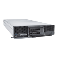
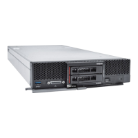
Figure 11. 2.5-inch hot-swap drive installation
Step 1. Identify the drive bay in which you plan to install the hot-swap drive.
Step 2. If a drive bay filler is installed, remove it from the compute node by pulling the release lever and
sliding the filler away from the compute node.
Step 3. Touch the static-protective package that contains the hot-swap drive to any unpainted metal
surface on the Lenovo Flex System chassis or any unpainted metal surface on any other grounded
rack component; then, remove the drive from the package.
Step 4. Open the release lever on the hot-swap drive and slide the drive into the bay until the lever catches
on the bezel, then rotate the handle to fully seat the drive.
Step 5. Lock the drive into place by closing the release lever.
Step 6. Check the drive status LEDs to make sure that the drive is operating correctly.
2.5-inch drive backplane replacement
Use the following information to remove and install a 2.5-inch drive backplane.
Remove the 2.5-inch drive backplane
Use this information to remove the 2.5-inch drive backplane.
Before you remove the 2.5-inch drive backplane, complete the following steps:
1. Read “Safety” on page iii and “Installation Guidelines” on page 21 to ensure that you work safely.
2. Power off the corresponding compute node that you are going to perform the task on.
3. Remove the compute node from the chassis (see “Remove the compute node from the chassis” on page
24).
4. Carefully lay the compute node on a flat, static-protective surface, orienting the compute node with the
bezel pointing toward you.
5. Remove the compute node cover (see “Remove the compute node cover” on page 42).
Notes:
28
ThinkSystem SN550 Compute Node Maintenance Manual

 Loading...


