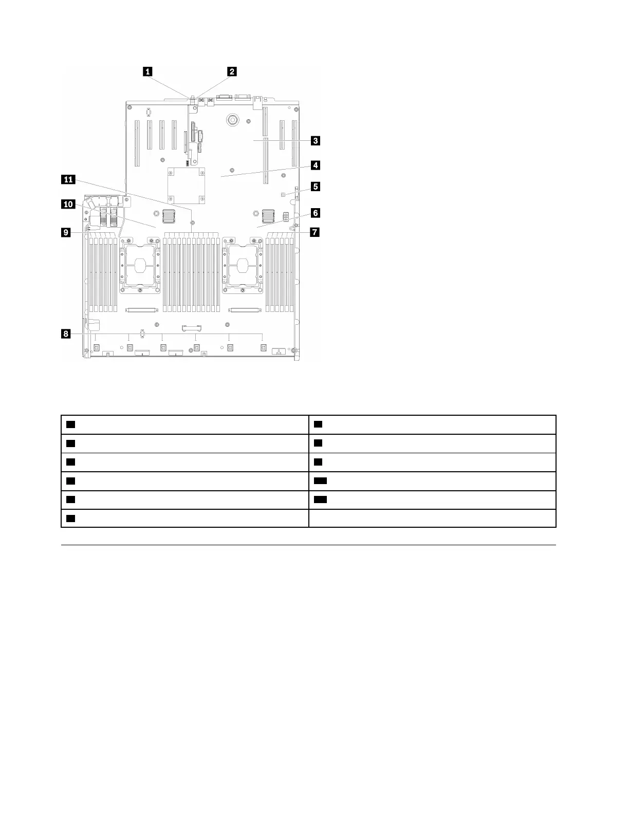
Figure 13. System-board LEDs
Table 12. System-board LEDs
1 System error LED (yellow)
7 DIMM 19-24 error LED
2 Identification LED (blue)
8 Fan 1-6 error LED
3 XCC heartbeat LED (Green)
9 DIMM 1-6 error LED
4 FPGA heartbeat LED (Green)
10 Processor 1 LED
5 Light path power LED 11 DIMM 7-18 error LED
6 Processor 2 LED
Optional processor and memory expansion tray
Use this information to locate the connectors and LEDs on the optional processor and memory expansion
tray.
The following illustrations show the connectors and LEDs on the processor and memory expansion tray.
24
ThinkSystem SR850 Maintenance Manual

 Loading...


