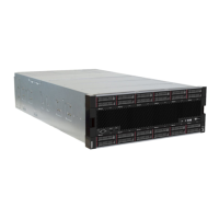
b. Slide the upper tray filler out from the front of the server.
c. Some cables may be packaged separately with the option, make sure all the cables are
connected correctly to the lower system board and upper system board in the compute tray.
See
http://thinksystem.lenovofiles.com/help/topic/7X12/cable_routing_common.html and http://
thinksystem.lenovofiles.com/help/topic/7X12/cable_routing_for_drives.html
.
d. Align the compute tray with the opening in the front of the chassis, and insert it.
e. Fully open the compute tray release levers, and push the compute tray into the chassis until it
stops.
f. Rotate the compute tray release levers towards the center until they lock and are fully closed.
g. Remove the fan fillers in fan bay 7 to 12, and install fans in those bays.
See
http://thinksystem.lenovofiles.com/help/topic/7X12/install_the_fan.html.
Step 9. If a storage tray is installed in the upper-tray position, you must convert it to a compute tray to take
advantage of eight processors.
Chapter 3. Server hardware setup 251
 Loading...


