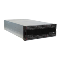
Note: Callouts for slots 1 to 4 apply when the riser is installed in the riser 1 position. Callouts for slots 10 to
13 apply when the riser is installed in the riser 2 position.
Figure 57. Slot 1 to 4 and slot 10 to 13 riser connectors
Table 224. Slot 1 to 4 and slot 10 to 13 riser connectors
Callout Callout
1 10 PCIe3 x8 (Slot 1 or 10) 3 12 PCIe3 x8 (Slot 3 or 12)
2 11 PCIe3 x8 (Slot 2 or 11) 4 13 PCIe3 x8 (Slot 4 or 13)
Slot 3 to 4 and slot 12 to 13 connectors
There are two PCIe3 x16, full height, half length connectors in the slot 3 to 4 and slot 12 to 13 riser.
Note: Callouts for slots 3 to 4 apply when the riser is installed in the riser 1 position. Callouts for slots 12 to
13 apply when the riser is installed in the riser 2 position.
Figure 58. Slot 3 to 4 and slot 12 to 13 riser connectors
Table 225. Slot 14 to 15 riser connectors
Callout Callout
3 12 PCIe3 x16 (Slot 3 or 12) 4 13 PCIe3 x16 (Slot 4 or 13)
Slot 10 to 15 riser connectors
There are five PCIe3 x16, full height, half length connectors and one ML2 PCIe3 x16 connector in the slot 10
to 15 riser.
288
ThinkSystem SR950 Setup Guide
 Loading...


