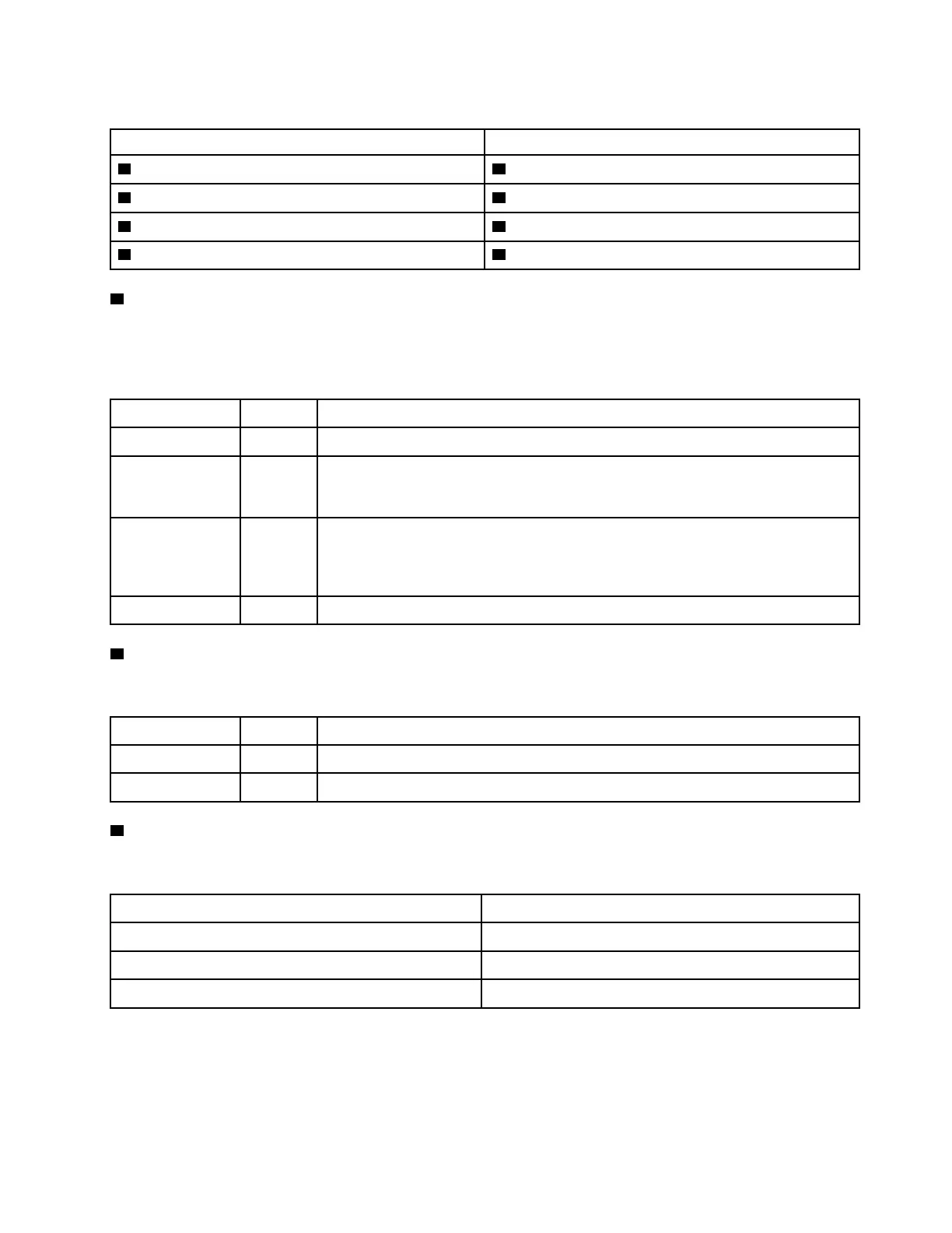
Table 3. Components on the front panel
Callout Callout
1 Power button with power status LED (green) 2 Simple-swap-drive activity LED (green)
3 Network activity LED (green) 4 System ID button with system ID LED (blue)
5 System error LED (yellow) 6 Opening for temperature sensor
7 XClarity Controller USB connector 8 USB 3.0 connector
1 Power button with power status LED
You can press the power button to turn on the server when you finish setting up the server. You also can hold
the power button for several seconds to turn off the server if you cannot turn off the server from the operating
system. The power status LED helps you to determine the current power status.
Status Color
Description
Solid on Green The server is on and running.
Slow blinking
(about one flash
per second)
Green The server is off and is ready to be powered on (standby state).
Fast blinking
(about four
flashes per
second)
Green The server is off, but the XClarity Controller is initializing, and the server is not ready
to be powered on.
Off
None There is no ac power applied to the server.
2 Simple-swap-drive activity LED
The simple-swap-drive activity LED is only for server models with simple-swap storage drives.
Status Color
Description
Solid on Green The simple-swap drive is active.
Off None The simple-swap drive is not active.
3 Network activity LED
Compatibility of the NIC adapter and the network activity LED.
NIC adapter NIC adapter
LOM adapter Support
ML2 NIC adapter Support
PCIe NIC adapter Not support
The network activity LED on the front panel helps you identify the network connectivity and activity.
Chapter 2. Server components 19

 Loading...


