Table 7. Components on the system board (continued)
Callout Callout
23 Intrusion switch connector
24 TCM
1
/TPM
2
connector (for only)
25 PCIe slot 6 (for processor 1) 26 PCIe slot 5 (for processor 2)
27 PCIe slot 4 (for processor 2) 28 PCIe slot 3 (for processor 1)
29 PCIe slot 2 (for processor 1) 30 PCIe slot 1 (for processor 1)
31 System fan 4 connector 32 Serial-port-module connector
Notes:
•
1
Trusted Cryptography Module
•
2
Trusted Platform Module
Internal cable routing
Some of the components in the server have internal cables and cable connectors.
To connect cables, observe the following guidelines:
• Turn off the server before you connect or disconnect any internal cables.
• See the documentation that comes with any external devices for additional cabling instructions. It might
be easier for you to route cables before you connect the devices to the server.
• Cable identifiers of some cables are printed on the cables that come with the server and optional devices.
Use these identifiers to connect the cables to the correct connectors.
• Ensure that the cable is not pinched and does not cover any connectors or obstruct any components on
the system board.
• Ensure that the relevant cables pass through the cable clips.
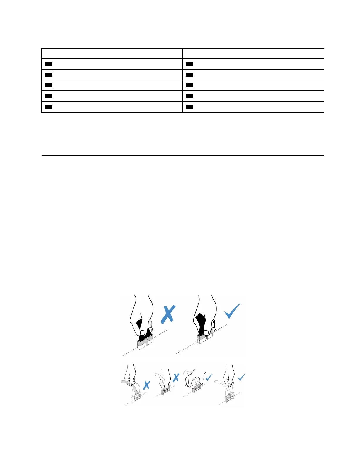
Note: Disengage all latches, release tabs, or locks on cable connectors when you disconnect cables from
the system board. Failing to release them before removing the cables will damage the cable sockets on the
system board, which are fragile. Any damage to the cable sockets might require replacing the system board.
Chapter 2. Server components 27

 Loading...


