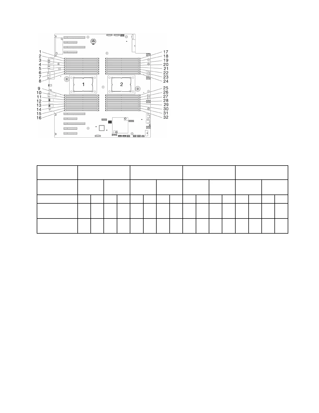
Figure 35. Processor and memory module layout
Table 18. Channel and slot information of DIMMs around processor
Memory
controllers
Controller 2 Controller 3 Controller 1 Controller 0
Channels Channel
1 (F)
Channel
1 (E)
Channel
1 (H)
Channel
0 (G)
Channel
0 (C)
Channel
1 (D)
Channel
1 (A)
Channel
1 (B)
Slots 1 0 1 0 1 0 1 0 1 0 1 0 1 0 1 0
DIMM numbers
(processor 1)
2 1 4 3 6 5 8 7 9 10 11 12 13 14 15 16
DIMM numbers
(processor 2)
31 32 29 30 27 28 25 26 24 23 22 21 20 19 18 17
DRAM DIMM installation order
This section contains information of how to install DRAM DIMMs properly.
Independent memory mode
In independent memory mode, memory channels can be populated with DIMMs in any order and you can
populate all channels for each processor in any order with no matching requirements. Independent memory
mode provides the highest level of memory performance, but lacks failover protection. The DIMM installation
order for independent memory mode varies based on the number of processors and memory modules
installed in the server.
Attention: Independent memory mode guidelines:
• There should be at least one memory module per processor.
• If only one DIMM is populated in a channel, populate it in the slot furthest away from CPU of that channel.
• Always populate DIMMs with a higher electrical loading in slot 0 followed by slot 1.
– When single or dual rank RDIMMs are populated for 2DPC, always populate the higher quantity rank
DIMM first in the farthest DIMM slot, followed by the nearest DIMM slot.
– If two DIMMs on a channel have identical ranks, then populate the one with the higher capacity on slot
0.
Chapter 4. Server hardware setup 63

 Loading...


