41
10 Indicating the setting of points / signals
Use the complementary set (art. no. 80145) to indicate the setting of
points and signals. The set comprises a 20-wire connecting cable and
32 yellow LEDs.
You must not connect light bulbs to the LW150!
If you want to use different LEDs, use so-called “low-
current” types. A series resistor is not required; it is
already integrated into the device (1kOhm). The voltage at
the outputs for the LEDs is 5V.
When initialising the Digital plus system, the LW150 will react in
accordance with the setting of DIP switch 8 (see the section "Setting
the startup characteristics" p. 32). If the setting of a point is
changed during operation (e.g. by means of a manual control) the
indicator of the LW150 will change, too. When using feedback-
enabled switch decoders LS100, a manual change of the setting of a
point is indicated, too (real feedback), provided the wiring of the
corresponding point drive has been effected correctly.
When using toggle switches (instead of keys), the LED
flashes if the setting of the switch does not correspond to
the setting of the point indicated by the command station.
As was the case when connecting keys, we recommend soldering the
stripped wires of the connecting cable for the LEDs to a customary
soldering strip. To facilitate orientation, the wires have been colour-
coded.
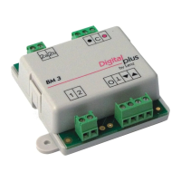
LEDs must be connected "the right way around". The two
connections of the LEDs are called "cathode" and "anode":