Information SET-01 91
DIGITAL plus
locomotive crosses the gap. One approach is to use a Digital Circuit
Breaker such as the LT100. If a locomotive bridges the insulated
gap, the module immediately interrupts the analog power supply.
Warning:
Mixed digital/analog operations using both rails and catenary
(overhead wire) is not allowed. In this mode of operation, if the
locomotive is on the track in the wrong direction (for instance after
going through a loop), the built-in locomotive decoder could be
destroyed by excessive voltage! We suggest you operate with
current pickup from the rails (wheel pickups), since that contact is
more reliable (and thereby the transmission of the digital signals to
the locomotive decoder) than with catenary.
17.8 Wiring the XpressNet Data Network
The XpressNet data network consists of 4 wires, 2 are for the signal
and two are for power that is used to power plugged in XpressNet
devices.
To install an XpressNet for SET-01 you need to insert an LA152
between the LH200 command station and the LV101 power station.
The 4 terminals on the LA152 labeled L,M,A and B are the 4
connections for the XpressNet. Connect these 4 wires to the
terminals with the same name on the LA150 connection board.
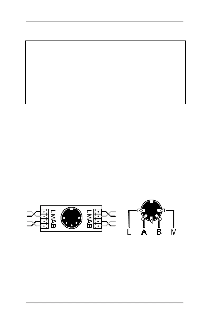
You can also solder the 4 wires to the DIN-sockets yourself. These
sockets are available in electronic-shops or in groups of five as part
XP-5 . The assignment of the five-pin DIN-socket is shown in the
following figure:
Connection Board LA150 21150 Pin Assignments from solder
side
Make sure that you do not mix up the cables of the terminals
L and M. This could result in a short in the connected input
devices.
The devices exchange information with the command station via the
cables at the terminals A and B. The devices are supplied with
electricity via the terminals L (plus) and M (minus).