Electrical installation
Wiring of the feedback system
Digital frequency input/output (encoder simulation)
5
130
EDKCSEX064 DE/EN/FR 6.0
Wiring
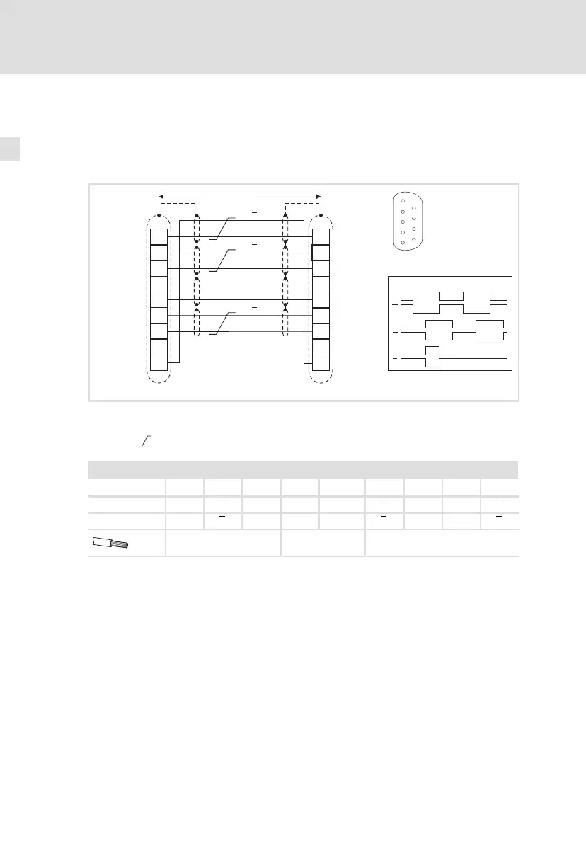
ƒ 1 slave on the master:
Wire master and slave to each other directly via interface X8.
B
GND
Z
1
2
3
4
5
6
7
8
9
1
2
3
4
5
6
7
8
9
A
<50m
A
B
Z
A
A
B
Z
B
Z
X8
(ECS-Slave)
X8
(ECS-Master)
5
1
9
6
ECSXA029
Fig. 5−15 Connection of the master frequency input/output X8 (master « slave)
Signals for clockwise rotation
Cores twisted in pairs
Assignment of plug connector X8: Sub−D 9−pole
Pin 1 2 3 4 5 6 7 8 9
Input signal B A A ˘ GND Z Z ˘ B
Output signal B A A ˘ GND Z Z ˘ B
0.14 mm
2
(AWG 26)
1 mm
2
(AWG 18)
0.14 mm
2
(AWG 26)
 Loading...


