Electrical installation
Wiring of the feedback system
Digital frequency input/output (encoder simulation)
5
131
EDKCSEX064 DE/EN/FR 6.0
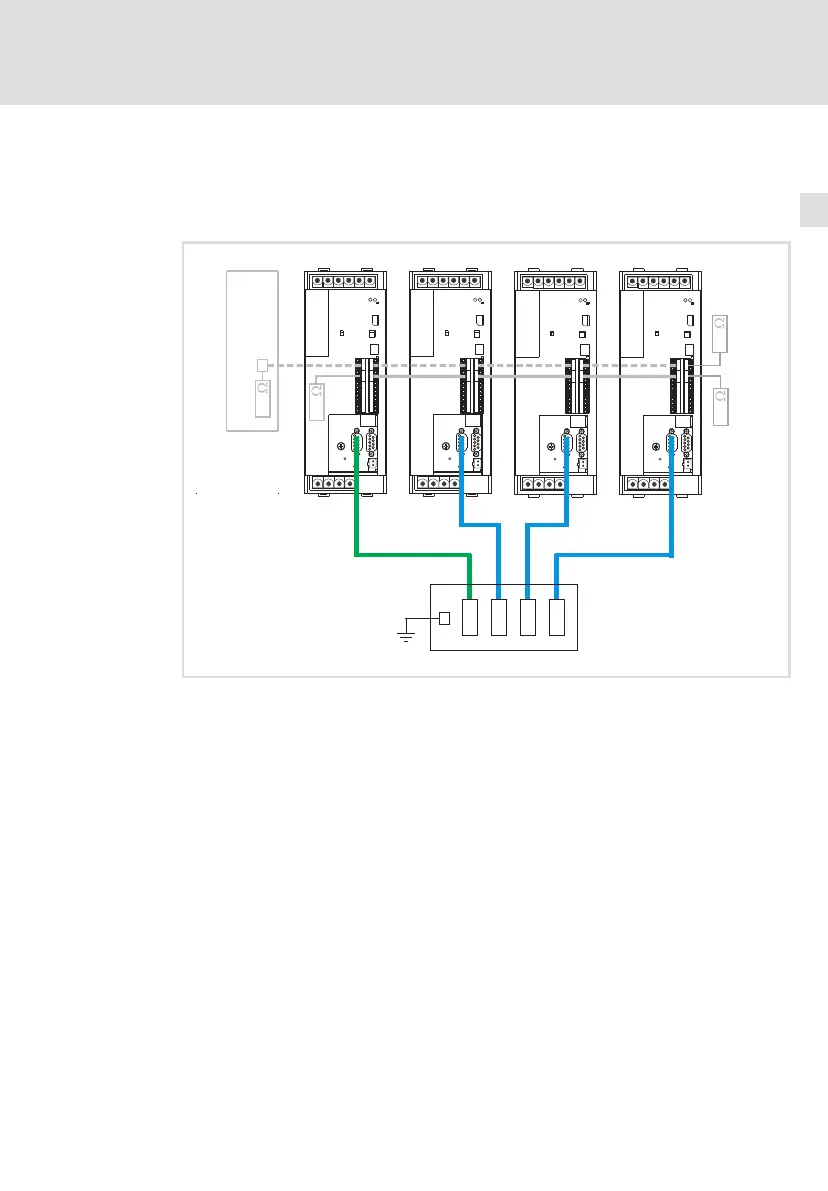
ƒ 2 to 3 slaves connected to the master:
Use the EMF2132IB digital frequency distributor to wire the ECS axis
modules with master digital frequency cable EYD0017AxxxxW01W01 and
slave digital frequency cable EYD0017AxxxxW01S01.
X8 X8 X8X8
0 111
E-Shaft Master Slave 3
Slave 2
Slave 1
X
S
PLC
X4X4
X4X4
120
ECS ECS ECS ECS
X1
X5
X2
X3
X4
EMF2132IB
120120
X14X14
X14X14
120120
120
ECSXP001
Fig. 5−16 ECS axis modules in the digital frequency network with digital frequency distributor
EMF2132IB
PLC Master control (PLC) or a PLC device to control the drive system
E−Shaft
master
Master value master (axis module ECSxP)
Slave 1...3 Slave 1, slave 2, slave 3 (axis module ECSxP)
Master digital frequency cable EYD0017AxxxxW01W01 (socket/socket)
Slave digital frequency cable EYD0017AxxxxW01S01 (plug/socket)
Tip!
"xxxx" in the type designation of the digital frequency cables
serves as a wildcard for the specification of the cable length in
decimetres.
Example: EYD0017A0015W01W01 ® cable length = 15 dm
 Loading...


