Monitoring functions
Configuring monitoring functions
Current load of controller (I x t monitoring: OC5, OC7)
9
235
EDBCSXM064 EN 11.0
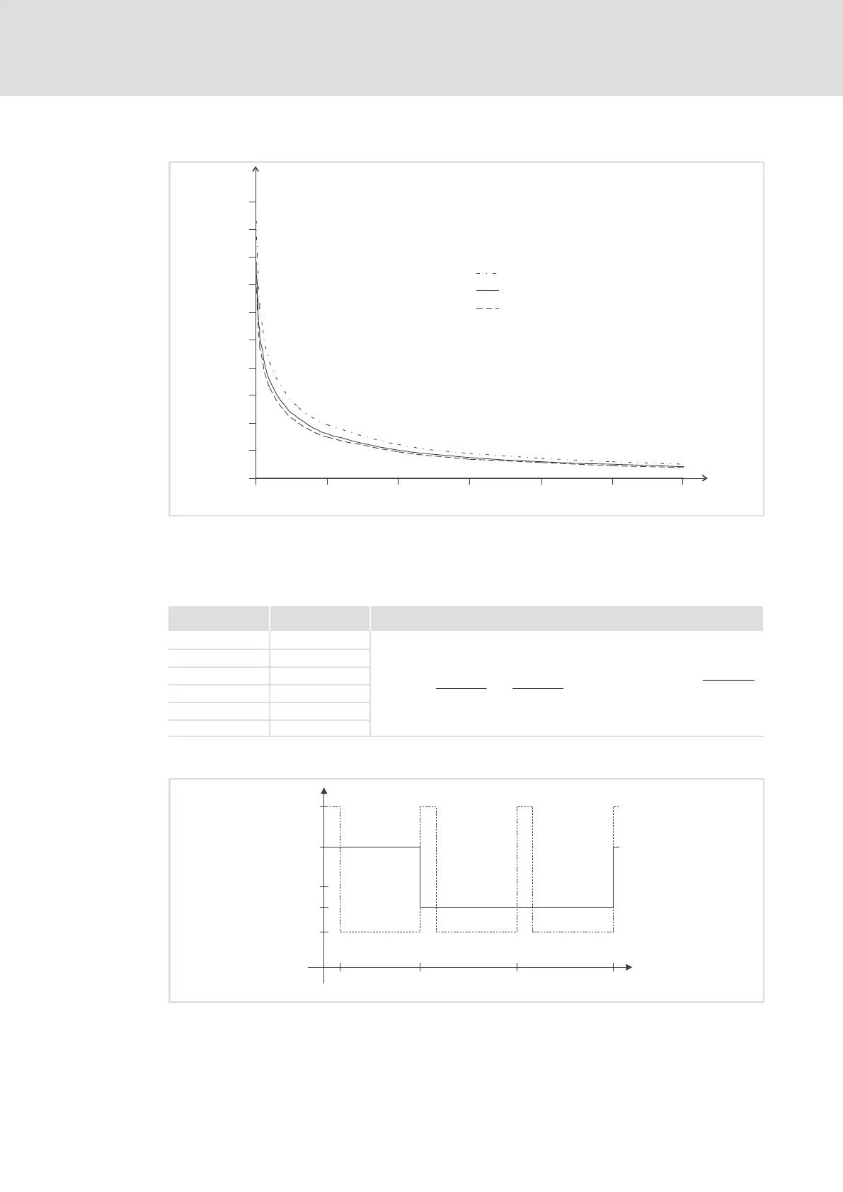
Overcurrent characteristic
0
20
40
60
80
100
120
140
160
180
200
1 1.5 2.0 2.5 3.0 3.5 4.0
t [s]
TRIP
I/I
r
ECSxS/P/M/A004, -008, -016, -032
ECSxS/P/M/A048
ECSxS/P/M/A064
ECSXA025
Fig. 9−1 Overcurrent characteristic ECSxM..., see also Rated data 32
The overcurrent characteristic shows the maximum time t
TRIP
till the axis module
generates an I x t error. In order to reach this time t
TRIP
again, the time 3 x t
axis
module
with
the load I/I
r
= 0 A must be observed.
Device
t
axis
module
[s]
Overcurrent characteristic
ECSxM004 54.6
I @ t +
I
subprofile_x
I
rated
*
ǒ
I
subprofile_x
I
rated
*I@ t
subprofile_x*1
Ǔ
@ e
*
t
subprofile_x
t
axis_module
ECSxM008 27.3
ECSxM016 27.3
ECSxM032 27.3
ECSxM048 29.5
ECSxM064 35.1
Overcurrent diagram for OC5 fault message
150
100
75
200
I [%]
Motor
10 60 120 180
t [s]
44
ECSXA293
Fig. 9−2 Maximum overcurrent as a function of time