Ordering information and accessories
Leuze electronic MLC 520 EX 60
425741 BT-10NC64 Sliding block with M6 and M4 thread, 10 x
425742 BT-10NC65 Sliding block with M6 and M5 thread, 10 x
Device columns
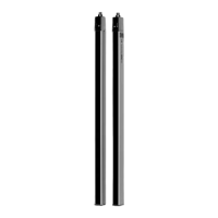
549855 UDC-900-S2 Device column, U-shaped, profile height 900 mm
549856 UDC-1000-S2 Device column, U-shaped, profile height 1000 mm
549852 UDC-1300-S2 Device column, U-shaped, profile height 1300 mm
549853 UDC-1600-S2 Device column, U-shaped, profile height 1600 mm
549854 UDC-1900-S2 Device column, U-shaped, profile height 1900 mm
549857 UDC-2500-S2 Device column, U-shaped, profile height 2500 mm
Deflecting mirror columns
549780 UMC-1000-S2 Continuous deflecting mirror column 1000 mm
549781 UMC-1300-S2 Continuous deflecting mirror column 1300 mm
549782 UMC-1600-S2 Continuous deflecting mirror column 1600 mm
549783 UMC-1900-S2 Continuous deflecting mirror column 1900 mm
Deflecting mirrors
529606 UM60-600 Deflecting mirror, mirror length 660 mm
529607 UM60-750 Deflecting mirror, mirror length 810 mm
529609 UM60-900 Deflecting mirror, mirror length 960 mm
529610 UM60-1050 Deflecting mirror, mirror length 1110 mm
529612 UM60-1200 Deflecting mirror, mirror length 1260 mm
529613 UM60-1350 Deflecting mirror, mirror length 1410 mm
529615 UM60-1500 Deflecting mirror, mirror length 1560 mm
430105 BT-2UM60 Mounting bracket for UM60, 2 x
Laser alignment aids
560020 LA-78U External laser alignment aid
520004 LA-78UDC External laser alignment aid for fastening in
Device Column
Test rods
349945 AC-TR14/30 Test rod 14/30 mm
349939 AC-TR20/40 Test rod 20/40 mm
Part no. Article Description

 Loading...