Electrical connection
Leuze electronic MLC 530 62
1 Changeover switch for switching between function groups FG1 and FG2
2 Key switch for teaching blanking areas
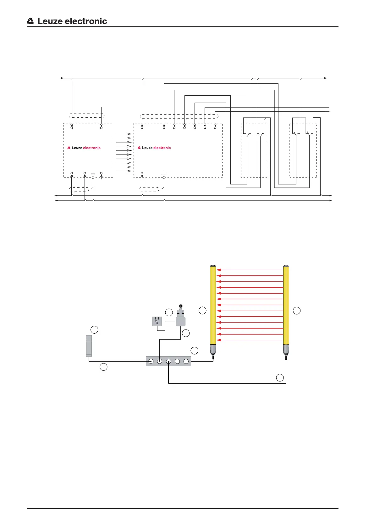
Figure 7.11: Operating mode 3: circuit diagram example of a linked, contact-based position switch for
monitoring of the blanked object and a changeover switch for switching between function
groups FG1 and FG2
1 MLC 500 transmitter
2 MLC 530 receiver
3 AC-SCM8 sensor connection module
4 S300 position switch + changeover switch
5 CB-M12-X000XE-2GF/GM connection cable
6 CB-M12-X000E-8GF connection cable
7 MSI-SR4 Safety Relay with RES and EDM
8 CB-M12-X000E-5GM connection cable
Figure 7.12: Operating mode 3: connection example with changeover switch for selecting function groups
and contact-based position switches
VIN2
7
IN3
3
VIN1
2
FE
-A2
MLC530R
IN4
4
IO1
1
+ 24V
FE
0V
+ 24V
FE
0V
-A4
OSSD2
5
OSSD1
8
IN8
6
WH
PK
GN
BN
BU
YE
GY
RD
VIN1
1
RNG
4
VIN2
3
FE
5
-A1
MLC500T
n.c.
2
WH
GY
BU
BN
BK
-A3
1
2
1
2
3
4
5
6
8
7
X1
X2
X3
X4
X5

 Loading...

