Figure B Figure D
"Bridged" Wire
Figure C
Retention Dust Cap
Cable
Management
Bar
5
Starting with the middle two pairs (orange/white and green/white)
use your fingers to carefully seat and secure the wires into the IDC
slots. Maintain wire pair twisting to within ½" (13 mm) of the IDC
contact. Then position a 110-style impact tool (set to low impact)
perpendicular to the IDC slot, seat and trim the cable.
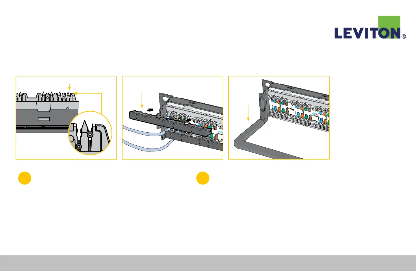
Note: If wires appear to be “bridged” over the IDC, rather than securely seated
into the slot, pull out the wires and reseat and repunch them (Figure B).
6
Once the Cat 6A module has been terminated, snap the 3-port
retention cap to the back of the connector top and bottom sides.
The retention cap can also be broken into single pieces (Figure C).
After the panel has been fully terminated, attach the cable
management bar to the back of patch panel (Figure D).
110-Style Patch Panel Termination Instructions Continued
Leviton Network Solutions
|
(800) 722 2082
|
+1 (425) 486 2222
|
leviton.com/ns 73
110-Style Patch Panel Termination Instructions