100 Ω UTP
4 Pair Twisted Pair Wire
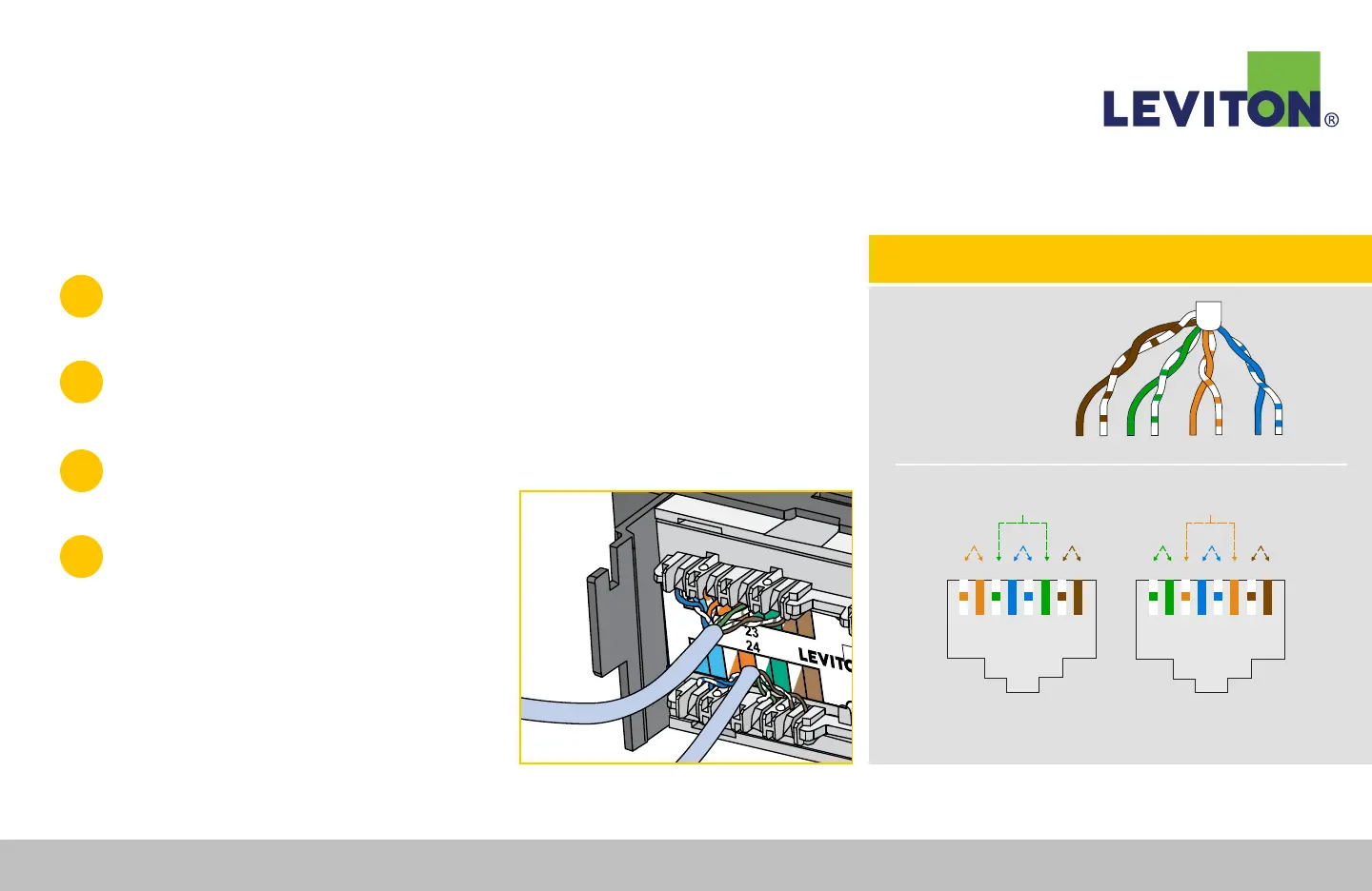
Category Rated / Plug Pinouts
NOTE: One of these wiring configurations must be used for an installation to be standard
compliant. Wiring label on connector shows both wiring standards.
TIPRING
PAIR 1
PAIR 2
PAIR 3
PAIR 4
TIPRING TIPRINGTIPRING
T568B
+ + + +- - - -
Pair1Pair2 Pair4
Pair3
T R T R T R T R
1 2 3 4 5 6 7 8
T568A
T R T R T R T R
1 2 3 4 5 6 7 8
+ + + +- - - -
Pair1Pair3 Pair4
Pair2
TECH TIP: Connector Wiring Guide and Color Code Key
110-Style Patch Panel Termination Instructions
1
Mount the Cat 6A 110-Style Patch Panel to a standard 19" equipment
rack or wall-mount bracket, using the provided screws.
2
Determine which color-coded wiring scheme is desired (T568A or T568B).
Note: The color codes and port numbers are located on the panel labels between termination (IDC) slots.
3
Remove approximately 3" (76 mm) of the
jacket and center spline/separator from cable.
4
Route jacketed wire to the termination field
so that the jacket is centered near the IDCs
(Figure A).
CAUTION: Use of mass termination impact tool is not
permissible for this product.
Figure A
Continued...
Leviton Network Solutions
|
(800) 722 2082
|
+1 (425) 486 2222
|
leviton.com/ns 72
110-Style Patch Panel Termination Instructions