User Manual for BPS-4H (High Temp.)
www.levitronix.com
PL-2009-03, Rev04, DCO# 21-101
4 Installation
4.1 Electrical Installation of the LC325P Controller
4.1.1 Overview
The LC325P controller has signal processor controlled power converters with four switched inverters for the
drive and the bearing coils of the motor. The signal processor allows precise control of pump speed and
impeller positioning.
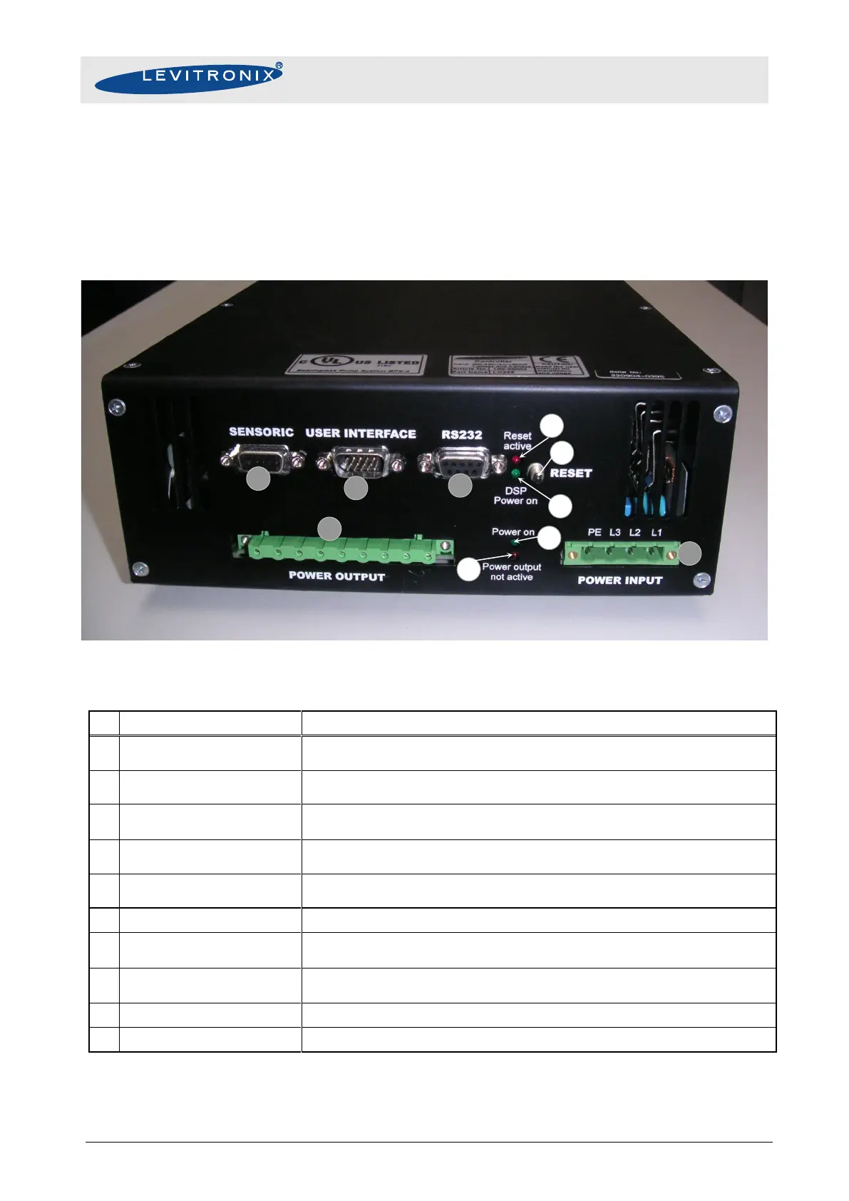
Figure 24: Connectors, RESET and LED’s of the LC325P controller
Sensor (radial position, field, temperature) signals from motor.
Torque spec. for tightening of connector screws on motor side: Min. = 0.4 Nm, Max. = 0.6 Nm
“USER INTERFACE” connector
Digital and analog I/Os. Interface for Levitronix PLC-interface-module.
Torque spec. for tightening of connector screws on motor side: Min. = 0.4 Nm, Max. = 0.6 Nm
Serial communication for service and operation purposes.
Interface to the control panel LUI-A or to the PC.
Drive and bearing currents of the motor.
1
Torque spec. for tightening of connector screws on motor side: Min. = 0.5 Nm, Max. = 0.6 Nm
AC power Input.
1
Torque spec. for tightening of connector screws on motor side: Min. = 0.5 Nm, Max. = 0.6 Nm
LED is on if supply voltage of signal electronics is present.
LED is on during the startup of the Digital Signal Processor and when the reset button is
pressed.
Red LED
“Power output not active”
LED is on if the switched output stages of the controller are disabled.
LED is on if the voltage supply (5 V and 12 V DC) for the power drivers is present.
Knob has to be pressed to reset of the controller.
Table 9: Connector, RESET and LED description of the LC325P controller
1: Connectors are not made for multiple connection cycles. Avoid connection cycles >25.