EasyManuals Logo

Levitronix BPS-4H Series User Manual

Levitronix BPS-4H Series
39 pages
To Next Page IconTo Next Page
To Previous Page IconTo Previous Page
Page #8 background imageLoading...
Page #8 background image
User Manual for BPS-4H (High Temp.)
www.levitronix.com
PL-2009-03, Rev04, DCO# 21-101
8
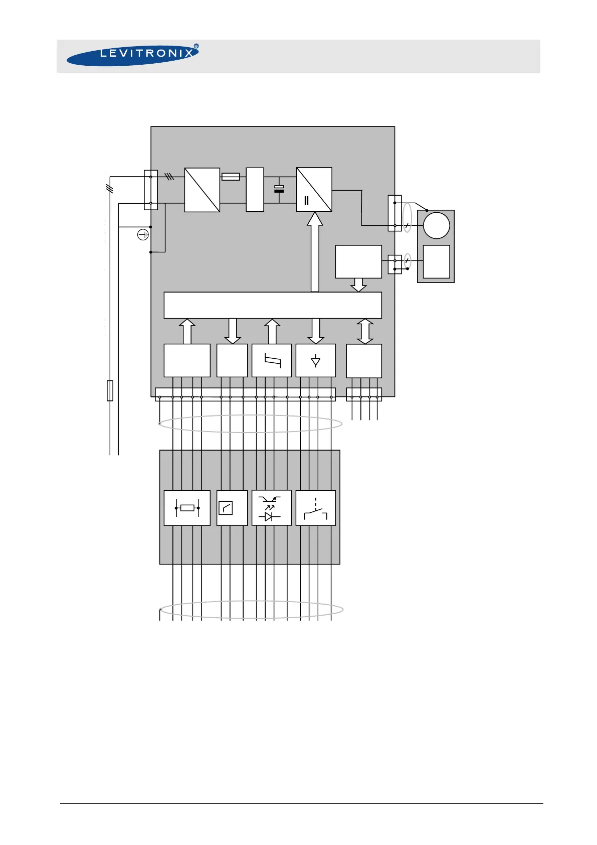
2.4 System Electronics
Figure 6: Block diagram and wiring pattern of the BPS-4 electronics for speed control
- PLC configuration for standard firmware with speed control
- For other configurations of PLC Inputs and Outputs refer to corresponding firmware documentation
DSP
D/A
A/D
RS232
2
3
5
1
15
5
3
10
14
8
4
13
9
6
7
11
12
2
1
brown +
violet -
orange +
gray -
black-
green +
red/blue-
blue +
white +
yellow/red +
yellow +
green/brown
pink
turquoise
red
Reference Value / Analog In1
Actual Process Control Value / Analog In2
Actual Speed / Analog Out1
Actual Process Control Value / Analog Out2
.
Reset / Digital In1
Process Mode / Digital In2
Enable / Digital In3
Status / Digital Out1
Error / Digital Out2
Warning / Digital Out3
Ground Analog In1
Ground Analog In2
Common Ground Digital In
Common Relay Contact Digital Out
Common Ground Analog Out
Shield
450 Ω
4-20mA
0-5V
10-24V, 10mA
1A / 30VDC
0.3A / 125VAC
TX
RX
GND
5V
1x AC 230V 10% L, N (L1, L2)
3x AC 208V10% L1, L2, L3
Minimum gage wire = AWG 18 ( = 1.02 mm)
PE
4~
LP
Controller LC325
PLC-Interface-Module
A/D
Position
Sensors
M
15
8
Motor BSM-4
DC
AC
PE
L, N (L1, L2)
or
L1, L2, L3
DC 325V 10%
or
DC 294V 10%
Filter
Fuse for all power lines
use only UL Listed Fuse
UL cat. JDYX
10A / 250V slow if LC325 is used
16A / 250V slow if LC325P is used
Protective earth

Table of Contents

Questions and Answers:

Question and Answer IconNeed help?

Do you have a question about the Levitronix BPS-4H Series and is the answer not in the manual?

Levitronix BPS-4H Series Specifications

General IconGeneral
BrandLevitronix
ModelBPS-4H Series
CategoryWater Pump
LanguageEnglish

Related product manuals