User Manual for BPS-4H (High Temp.)
www.levitronix.com
PL-2009-03, Rev04, DCO# 21-101
4.3 Mechanical Installation of the Pump Head with Motor
▪ For mounting of the motor use 4 M8 screws through the holes in the mounting foot located on the
motor as illustrated in Figure 11. As an alternative for mounting the motor the 4 tapped holes (size M6)
in the bottom of the motor as shown in Figure 11 can be used.
▪ Minimum cable bending radius according Table 6 to shall be followed for the installation of the motor
and extension/adaptor cables
▪ Attach a cooling water circuit to the connections of the motors integrated cooling loop (Figure 11). Do
not remove the twisting protection as this might unscrew the cooling connections of the motor and
result in leakage of the cooling fluid.
▪ For double safety against chemical hazards it is required to place the pump head with the motor in a
contained enclosure.
Twisting protection of the cooling loop connectors of the motor.
Do not remove the twisting protection (Figure 11) as this might unscrew the
cooling connectors of the motor and result in leakage of the cooling fluid.
TOXIC CHEMICALS may be present.
When using the system to pump chemicals, skin contact and toxic gases may
be hazardous to your health. Wear safety gloves and other appropriate safety
equipment.
For double safety it is required to place the pump head with the motor in a
contained enclosure.
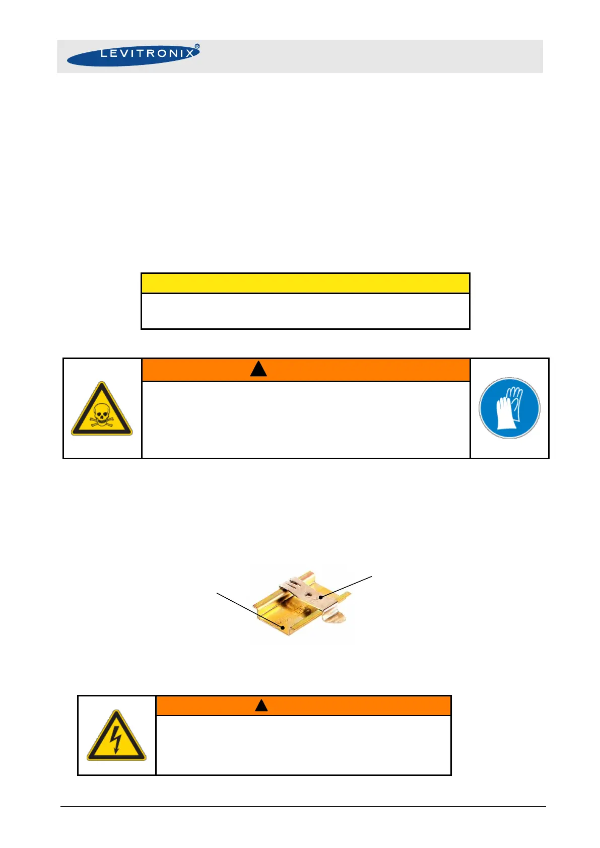
4.4 Mechanical Installation of the LC325P Controller
To mount the controller, use the two din-rail brackets on the controller housing (see Figure 13).
Figure 28: Din-rail bracket for mounting of the LC325P controller
Hazardous voltage may be present.
In order to avoiding fluid spills shorting mains or other voltages within
the controller, place the controller in a spill protected electrical cabinet.
If explosive flammable gases are present, place the controller in an
explosion-proof cabinet.