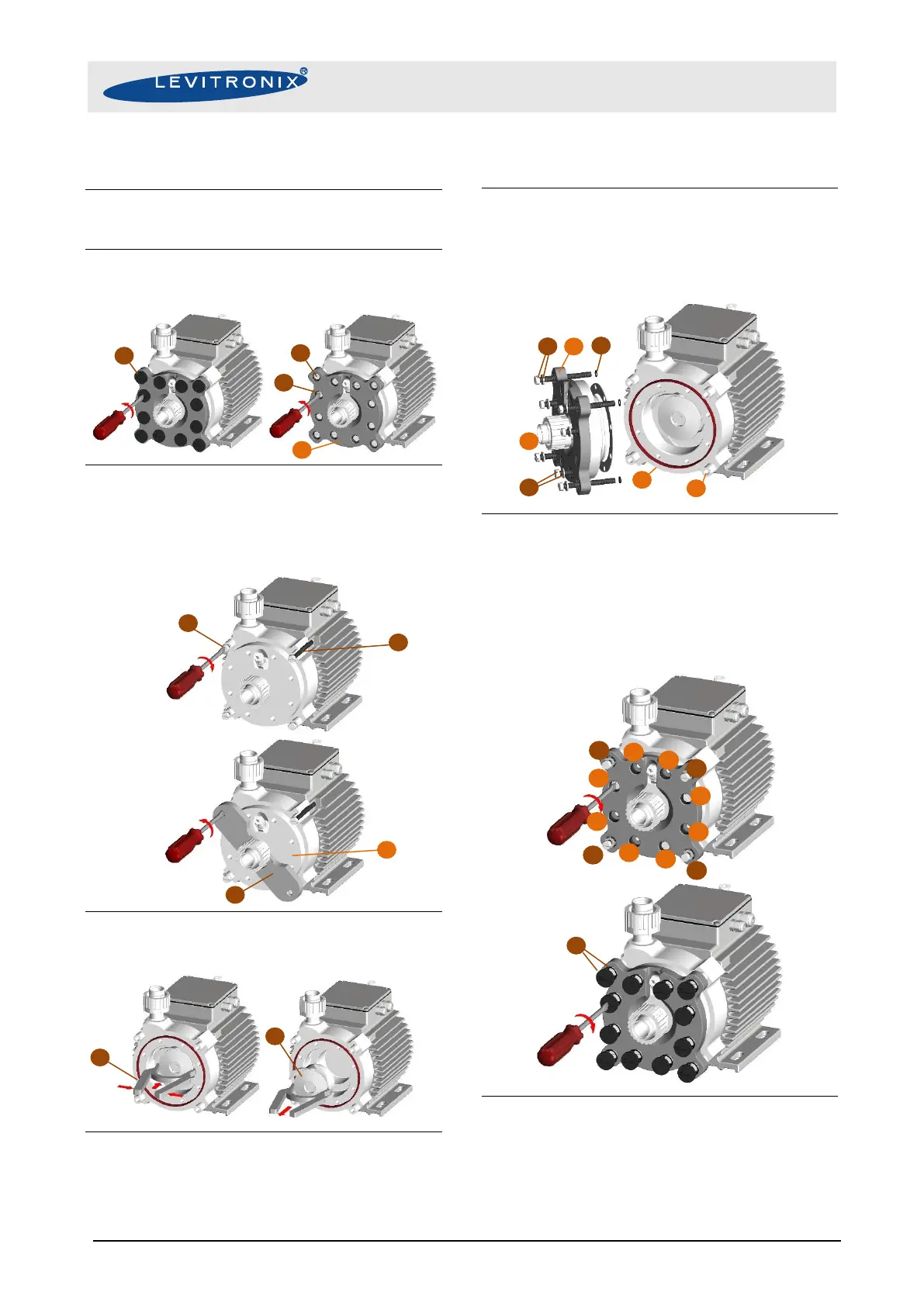
Instructions for Impeller Replacement
1. Power down the pump system and remove the AC
power. If necessary, allow the housing to cool down to
a workable temperature.
2. Unscrew the 12 Screw Protection Cups (E), the 4
Motor Screws (C), the 8 Pump Head Screws (D) and
remove the Axial Support plate (a).
3. Fix the pump head with 4 Motor Screws (C) on the
motor. Place the Housing Removal Tool (H) under the
fitting of the Lid (b) and rotate it until 2 Motor Screws
are covered by the holes. Unscrew the 2 Motor
Screws (C) below the Housing Removal Tool (H)
alternately until the lid can be removed by hand.
4. Remove the Impeller (A) with the Impeller Exchange
Tool (G). Hook the claws of the Impeller Exchange
Tool (G) into two opposing orifices of the impeller.
5. Inspect the wet area of the pump casing carefully. In
case of material damage, also replace the pump
casing. Place the new Impeller (A) into the pump
casing using the Impeller Exchange Tool (G). If
necessary, remove the existing Back-Up Gasket (B).
6. Add the 4 Screw Protection Pipes (e) into the
according sinkholes of the Casing Bottom (c). Then fit
the Axial Support Ring (a) with the Casing Lid (b) and
add all Motor Screws (C) and 8 Pump Head Screws
(D) including the Spring Washers (C+D) and the Pipe
O-Rings (F). Pay attention during align the Back-Up
Gasket (B). Then place this to the Casing Bottom (c).
7. Tighten first the 4 Pump Head Screws Motor Screws
(C) (all including the Spring Washers) stepwise
screwing down alternately each screw in the
sequences (C1-4, 17 Nm) and the 8 further Pump
Head Screws (D1-8, 3.5 Nm) and then the specified
below. After 30 minutes re-tighten all screws with the
specified torque. Finally screw (1.5 Nm) on the Screw
Protection Cups with the O-Rings (E). All screw
torques are defined in Figure 34.
8. Start up the system and check if the impeller is
rotating properly and the pump head is not leaking. If
the pump head leaks, check and make sure the
casing lid is properly pressed into the bottom of the
pump casing. Also check the torque of the pump
head screws.