You can use the pump to pump water vapour. You must use the gas ballast
when water vapour is pumped. The water vapour must not condense in the
pump.
To use the pump for a gas that is not listed, contact the supplier for advice.
Failure to contact the supplier can invalidate the warranty of the pump. Do
not use the pump for aggressive or corrosive gases.
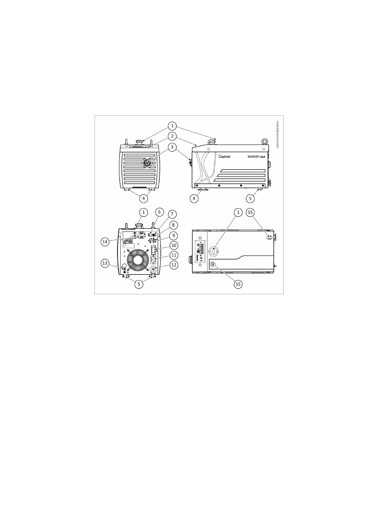
Figure 1. General view
1. Inlet port 2. Dashboard or interface
3. Gas ballast 4. Vibration isolator
5. Castors x 2 6. X101, RJ45 connector
7. X201, M8 Aux Connector 8. X1 SUB-D 9 pin (male)
9. X104 SUB-D 9 pin (female) 10. Mains circuit breaker
11. Mains connector socket 12. Exhaust port
13. Protective earth stud 14. Voltage selection cover plate
15. Lifting eye position
2.2 Pump controller
The pump controller contains the drive electronics to control the pump
operation. The pump controller controls the supply of electric current to the
motor as per the operating conditions.
The interface control panel is connected to the pump controller. The pump
can be operated:
▪ manually, with the buttons on the user interface control panel. Refer to
Figure: Interface control panel.
▪ remotely, with the serial communications (X104) or digital and analogue
process control (X1), through the SUB-D 9 pin connector. Refer to
Connection for remote control and monitoring on page 23.
300902516_002 - 10/2020 - © Leybold
10
General description