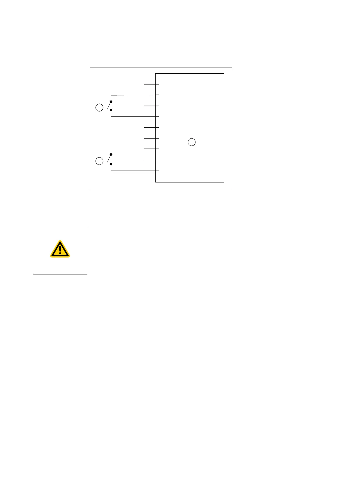
Figure 8. ECODRY plus X1 SUB-D 9 (male) START / STOP and STANDBY operation
conguration
STANDBY Enable Input
1
2
3
4
5
6
7
8
9
= START / STOP Control Input
=
0 V Control Reference
=
3
2
1
G20/AVG/GCN/0006/005/A
1. START/STOP switch 2. STANDBY switch
3. Logic control interface
1. START/STOP switch 2. STANDBY switch
3. Logic control interface
6.5 Analogue speed control
CAUTION: CONNECTION SAFETY
Risk of damage to equipment. Physical connection to the analogue speed input (X1,
pin 6) and the gauge input (X101) at the same time, will result in the wrong speed
control reference signal. For correct operation of the analogue speed input, all
physical connections to the gauge input must be removed.
The analogue speed input (X1, pin 6) is a process control source that
enables the pump to run at variable operating speeds. This speed control
source is an alternative to STANDBY speed control. Furthermore, the
analogue speed input cannot be used if the gauge input is active.
The analogue speed input functionality is disabled by default. To enable this
functionality, the ECODRY plus service tool must be used to congure the
pump for analogue speed control. Please contact your local distributor for
more details.
29
300902516_002 - 10/2020 - © Leybold
Operation