Installation
GA09420_002_C0 – (2016-10) –
Leybold
21
WARNING
The supply common (Pin 5) and the shielding (Pin 15) must be
connected at the supply unit with protective ground.
Incorrect connection, incorrect polarity or inadmissible supply
voltages can damage the transmitter.
For cable lengths up to 5 m (0.34 mm
2
conductor cross-section) the out-
put signal can be measured directly between the positive signal output
(Pin 2) and supply common GND (Pin 5) without loss of accuracy. At
greater cable lengths, differential measurement between signal output
(Pin 2) and signal common (Pin 12) is recommended.
Reassemble the cable connector.
On the other cable end, terminate the cable according to the requirements
of the transmitter controller you are using.
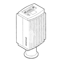
Plug the sensor connector into
the transmitter and secure it with
the locking screws.
Connect the other end of the sensor cable to the connector of the instru-
ment or transmitter controller you are using.
The transmitter can now be operated via analog and RS232C interface.
 Loading...