Installation
35300324726_002_C0 - 10/2016 - © Leybold
3.7 Electrical connection for the integrated frequency converter
Observe Safety Informations 0.2.
Disconnect and connect the cable connections only while the pump is
turning no longer (green status LED off) and with the mains power
switched off (yellow power LED off). Other wise there is the risk of damag-
ing the frequency converter.
The interface connectors have UNC 4-40 threads. Do not use connectors
with M3 treads.
The pump may be operated only with suitable connector cables.
Route all cables so, as to protect them from damage.
Plug in the mains cable. Refer to Fig. 3.12 for the mains plug connection.
In order to comply with the standard SEMI S2, install an additional mains
power circuit breaker at the sides of the system. The short-circuit switch-off
capacity of this mains power circuit breaker needs to be rated at 10,000 A
minimum.
DANGER
NOTICE
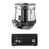
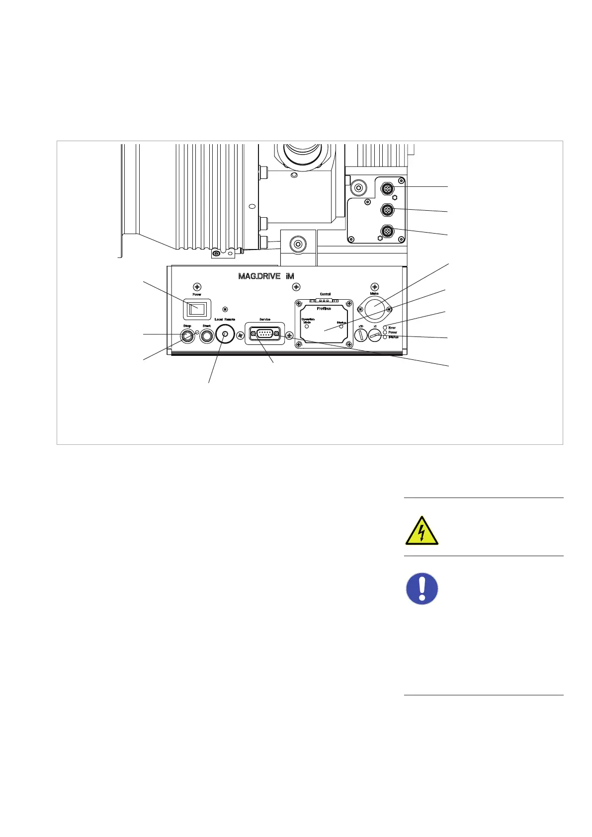
Fig. 3.11 View of the integrated frequency converter
UNC 4-40 threads
1) Profibus or another optional interface
Connection for
24 V DC valves:
Purge gas
Venting
Cooling water
Mains cable
Interface
1)
LEDs
Address switches
Service interface
(RS 232)
Main switch
(do not use to
stop the pump!)
Start/Stop keys
LED Local/Remote,
lights at Local
Swich Local/Remote,
(under a cover)
 Loading...