Installation
37300324726_002_C0 - 10/2016 - © Leybold
Red LED ERR
off: No error, no warning
flashes: Warning is present, pump can be
operated, possibly with some restrictions
on: Fault is present, pump stopped or
can not be operated
Yellow LED PWR
off: No supply voltage
flashes: Supply voltage too low or too high,
9 Hz <n <100Hz (venting possible)
on: Supply voltage is present
Green LED STS
off: Pump at standstill (< 9 Hz)
flashes slowly 1/s: Start command is present
(flashes fast 3/s: Running down, brake operation:
option)
flashes shortly (0.3 s): Start delay active
on: Normal operation
Yellow LED PWR and green LED STS
(flash fast Running down, brake operation at n < 100 Hz
alternately i.e. venting is possible:
option)
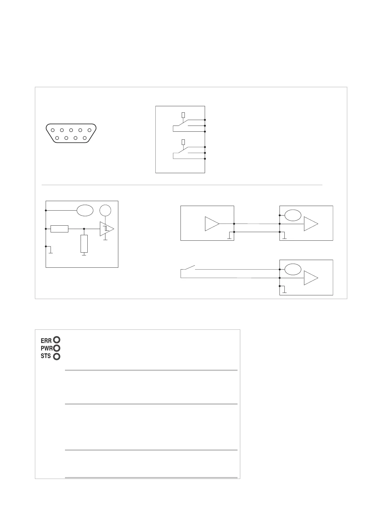
Front LEDs
Relay functions
876
54321
9
Pin assignment of the connector
5
3
4
n. c.
n. o.
com.
2
9
1
n. c.
n. o.
com.
Relay - Normal operation (standard setting)
■ While deceleration, acceleration, Stop:
4 connected to 5 (as shown; passive)
■ During normal operation (f > 0,9·f
nom.
):
4 connected to 3 (active)
Relay - Error
■ No error: 1 connected to 2 (as shown; passive)
■ Error is present: 1 connected to 9 (active)
Fig.3.13 Pin assignment of the PLC interface (optional for CONTROL connector)
MAG.DRIVE
12-15 V
1.8 kΩ
3.3 kΩ
MAG 300
7
8
6
MAG 300
7
8
6
0 V = STOP
12-24 V = START
MAG 300
7
8
6
12-15 V
12-15 V
Pin assignment for the Start/Stop input
Switching threshold
for the Start/Stop
control input:
Low level: < 8 V
High level: > 10.5 V
Start/Stop operation
Example 1: Operation via a PLC
Contact open = STOP
Contact closed = START
Example 2: Operation via contacts
PLC interface
Only for SELV or PELV power circuits up to 32 V, maximum current 0.5 A
0 V = STOP
12-24 V = START
MAG
MAG
MAG
 Loading...