Installation
18
GA 05.139/1.02 - 06/99
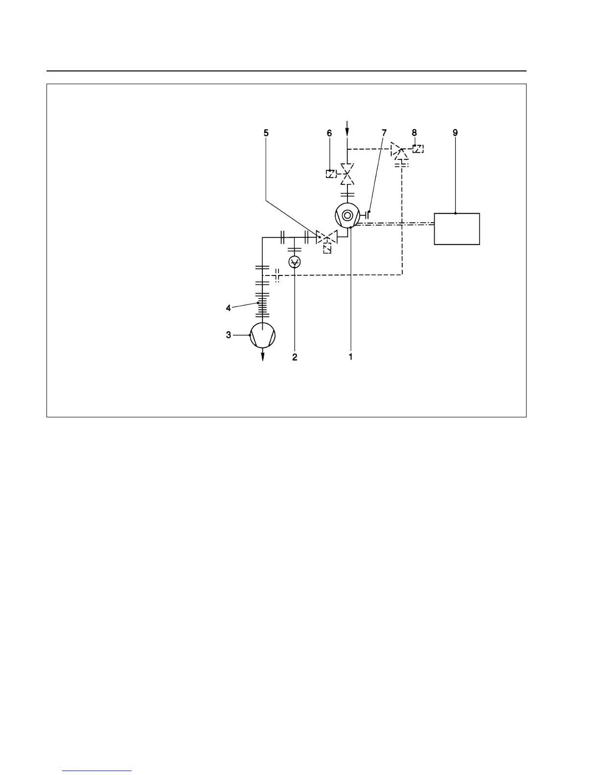
Fig. 16 Layout of a turbomolecular pump system
Key to Fig. 16
1 Turbomolecular pump
2 Forevacuum gauge point
3 Backing pump
4 Anti-vibration bellows
5 Forevacuum valve
6 High vacuum valve
7 Purge gas connection
8 Valve in the roughing line
9 Electronic frequency converter
— — — — roughing line; recommended
if shorter cycle times are to be achieved
— · — · — · — · BEARING and DRIVE/TMS cable
 Loading...