Operation
16
3.2.1 9-way PLC inter face
Controlling the instrument through the keys START and STOP and the 9-way
PLC interface has equal priority.
The control lines for the interface respond to the rising or falling flank of a
+24 V DC signal.
When the pump is started through X1 and then the STOP key is pressed,
the pump will be switched off, but 24 V is still present at X1. For starting the
pump through X1 give a stop signal at first and then a start signal.
The same applies vice versa: When a stop signal is present at X1 and the
pump is started with the START key, give a start signal at first and then a
stop signal for stopping the pump.
When switching on the Turbo.Drive TD20
classic
the status at X1 will be uti-
lized.
The other (optional) interfaces behave differently. When controlling the instru-
ment through them, the keys are disabled (except from the start-up).
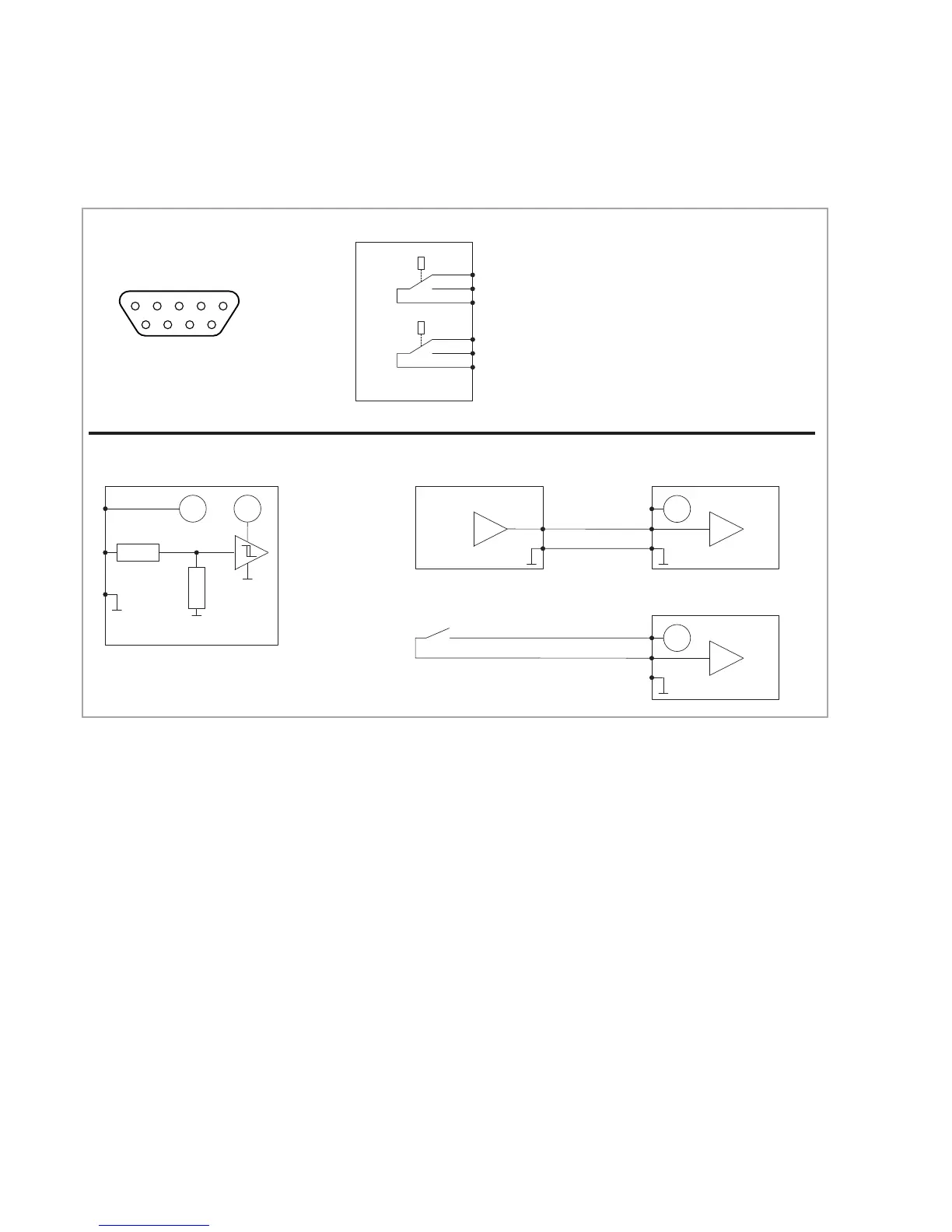
Fig. 3.2 9-way PLC inter face X1
876
54321
9
Pin assignment of the connector
24 V
5 V
5 kΩ
2 kΩ
Turbo.Drive TD20
classic
7
8
6
24 V
7
8
6
0 V = STOP
24 V = START
24 V
7
8
6
max. 80 mA
TD20
classic
TD20
classic
Pin assignment for the Start/Stop input
Switching threshold
for the Start/Stop
control input:
Low level: < 8 V
High level: > 10,5 V
Start/Stop operation
Example 1: Operation via a PLC
Contact open = STOP
Contact closed = START
Example 2: Operation via contacts
Relay functions
TURBO.DRIVE S
5
3
4
n. c.
n. o.
com.
2
9
1
n. c.
n. o.
com.
Relay - Normal operation
n While deceleration, acceleration, Stop:
4 connected to 5 (as shown; passive)
n During normal operation (f > 0.8·f
nom.
):
4 connected to 3 (active)
Relay - Error
n No error: 1 connected to 2 (as shown; passive)
n Error is present: 1 connected to 9 (active)
TD20
classic
Turbo.Drive TD20
classic
Contact rating: 2A / 50V DC max. (resistive load)
 Loading...