REFRIGERANT DESIGN | 67
Refrigerant Piping Design & Layout Best Practices
Due to our policy of continuous product innovation, some specications may change without notication.
©
LG Electronics U.S.A., Inc., Englewood Cliffs, NJ. All rights reserved. “LG ” is a registered trademark of LG Corp.
REFRIGERANT PIPING DESIGN
No Pipe Size Substitutions
Using a different size is prohibited and may result in a system malfunction or failure to work at all.
In-line Refrigeration Components
Components such as oil traps, solenoid valves, filter-dryers, sight glasses, tee fittings, and other after-market accessories are not permitted
on the refrigerant piping system between the outdoor unit and the indoor unit. Single Zone Wall Mount systems are provided with redundant
systems that assure oil is properly returned to the compressor. Sight-glasses and solenoid valves may cause vapor to form in the liquid
stream. Over time, dryers may deteriorate and introduce debris into the system. The designer and installer should verify the refrigerant
piping system is free of traps, sagging pipes, sight glasses, filter dryers, etc.
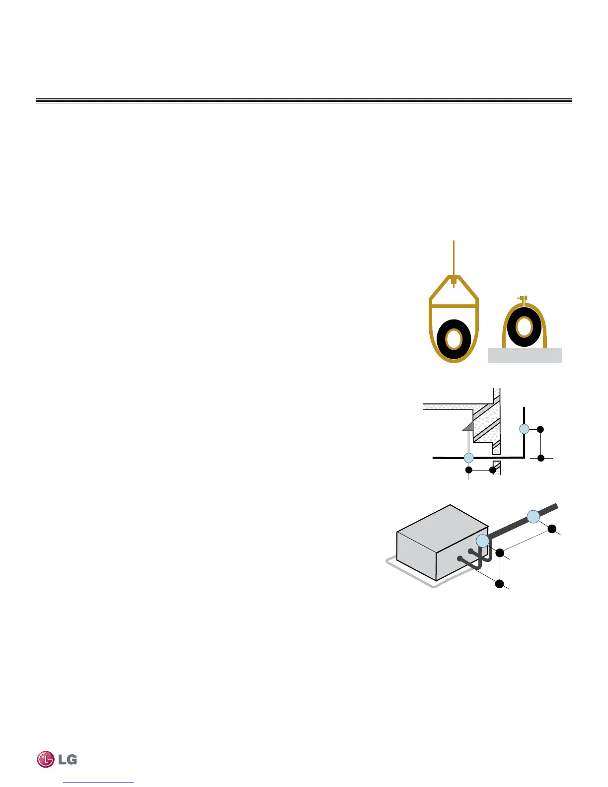
Pipe Supports
A properly installed pipe system should be adequately supported
to avoid pipe sagging. Sagging pipes become oil traps that lead to
equipment malfunction.
Pipe supports should never touch the pipe wall; supports shall be
installed outside (around) the primary pipe insulation jacket (see
Figure 31). Insulate the pipe first because pipe supports shall be
installed outside (around) the primary pipe insulation jacket. Clevis
hangers should be used with shields between the hangers and
insulation. Field provided pipe supports should be designed to
meet local codes. If allowed by code, use fiber straps or split-ring
hangers suspended from the ceiling on all-thread rods (fiber straps
or split ring hangers can be used as long as they do not compress
the pipe insulation). Place a second layer of insulation over the pipe
insulation jacket to prevent chafing and compression of the primary
insulation within the confines of the support pipe clamp.
A properly installed pipe system will have sufficient supports to avoid
pipes from sagging during the life of the system. As necessary,
place supports closer for segments where potential sagging could
occur. Maximum spacing of pipe supports shall meet local codes.
If local codes do not specify pipe support spacing, pipe shall be
supported:
• Maximum of five feet (5′) on center for straight segments of pipe up
to 3/4" outside diameter size.
Wherever the pipe changes direction, place a hanger within twelve
(12) inches on one side and within twelve to nineteen (12 to 19)
inches of the bend on the other side as shown in Figure 32.
Figure 32: Pipe Hanger Details.
Figure 33: Typical Pipe Support Location—
Change in Pipe Direction.
Figure 34: Pipe Support at
Indoor Unit.
Max. 12"
~ 12" – 19"
Refrigerant Piping System Layout

 Loading...