66 | REFRIGERANT DESIGN
Single Zone High Efciency and Standard Wall Mount Engineering Manual
Due to our policy of continuous product innovation, some specications may change without notication.
©
LG Electronics U.S.A., Inc., Englewood Cliffs, NJ. All rights reserved. “LG ” is a registered trademark of LG Corp.
INSTALLATION & LAYOUT BEST PRACTICES
Refrigerant Piping System Layout
Physical Pipe Length: Actual length of straight segment(s) of pipe.
Equivalent Pipe Length: Actual length of pipe plus equivalent lengths of elbows, Y-branches, and valves.
1. Draft a one-line diagram of the proposed piping system connecting outdoor unit to heat recovery and indoor units. Follow the pipe
limitations listed on page 64.
2. Calculate the physical length of each pipe segment and note it on the drawing.
3. Calculate the equivalent pipe length of each pipe segment.
Using Elbows
Field-supplied elbows are allowed as long as they are designed for use with
R410A refrigerant. The designer, however, should be cautious with the quantity
and size of fittings used, and must account for the additional pressure losses in
equivalent pipe length calculation. The equivalent pipe length of each elbow must
be added to each pipe segment. See Table 40 for equivalent lengths.
Table 40: Equivalent Piping Length for Piping Components.
Definitions
Layout Procedure
Component
Size (Inches)
1/4 3/8 1/2 5/8 3/4
Elbow (ft.)
0.5 0.6 0.7 0.8 1.2
Field-Provided Isolation Ball Valves
It is acceptable to install field-supplied ball valves with Schrader ports at the indoor unit. Full-port isolation ball valves with Schrader ports
(positioned between valve and indoor unit) rated for use with R410A refrigerant should be used on both the liquid and vapor lines.
If valves are not installed and the indoor unit needs to be removed or repaired, the entire system must be shut down and evacuated. Position
valves with a minimum distance of three (3) to six (6) inches of pipe on either side of the valve. Valves must be easily accessible for service.
If necessary, install drywall access doors or removable ceiling panels, and position the valves to face the access door or ceiling panel open-
ing. Mount valves with adequate space between them to allow for placement of adequate pope insulation around the valves. Recommended
best practice is to clearly label and document locations of all service valves. The equivalent pipe length of each ball valve must be added to
each pipe segment.
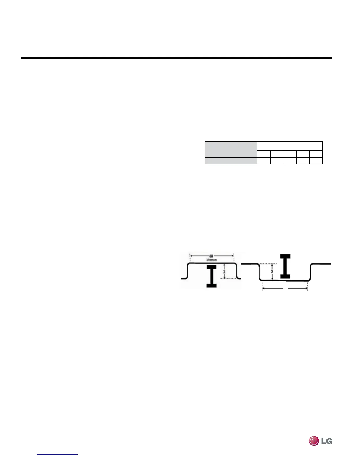
Obstacles
When an obstacle, such as an I-beam or concrete T, is in the path
of the planned refrigerant pipe run, it is best practice to route the
pipe over the obstacle. If adequate space is not available to route
the insulated pipe over the obstacle, then route the pipe under the
obstacle. In either case, it is imperative the horizontal section of pipe
above or below the obstacle be a minimum of three (3) times greater
than the longest vertical rise (or fall) distance. Refer to Figure 31.
Figure 31: Installing Piping Above and Below an Obstacle
Above an obstacle.
3X
Below an obstacle.

 Loading...