REFRIGERANT DESIGN | 71
Refrigerant Piping Design & Layout Best Practices
Due to our policy of continuous product innovation, some specications may change without notication.
©
LG Electronics U.S.A., Inc., Englewood Cliffs, NJ. All rights reserved. “LG ” is a registered trademark of LG Corp.
ELECTRICAL CONNECTIONS
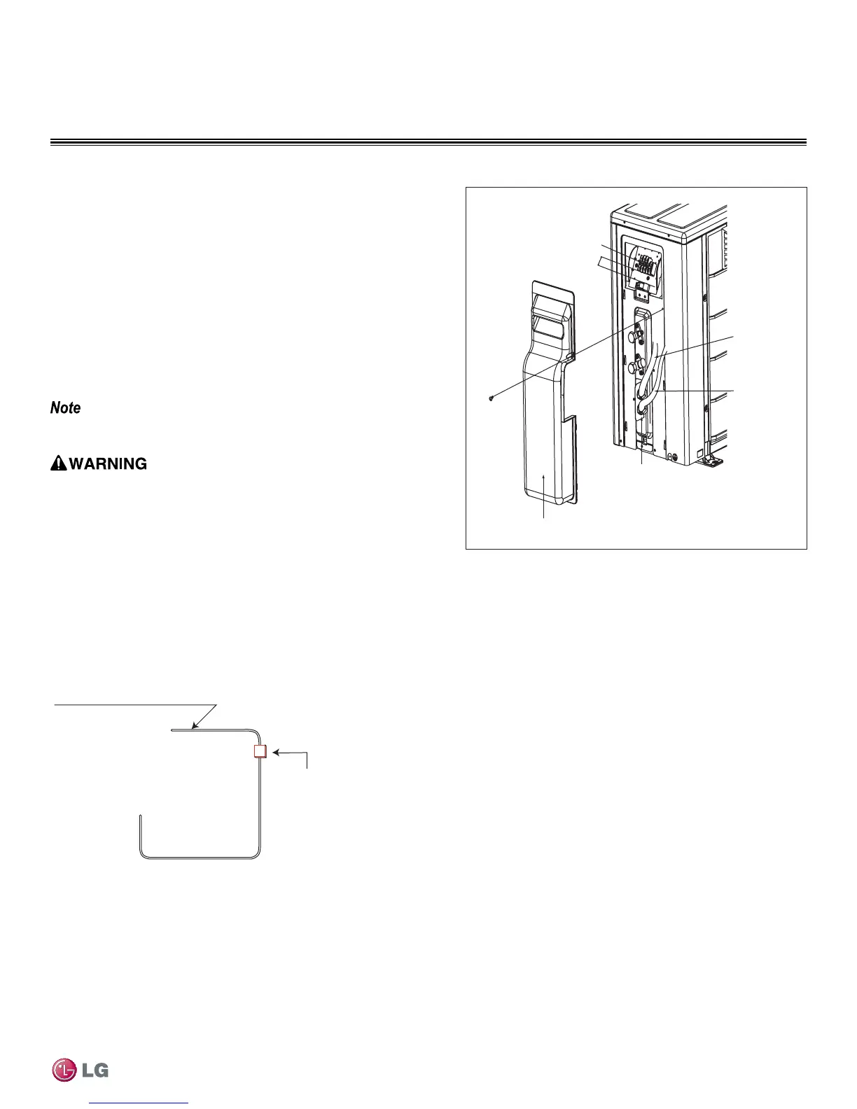
Figure 41: Outdoor Unit Connection
Terminal Block
Connecting
Cable
Power
Supply
Cord
Conduit Panel
Tubing Cover
Over 0.2”
Outdoor Electrical Connection
1. Remove the control cover from the unit by loosening the fastening
screw. Refer to Figure 41.
2. Take off the caps on the conduit panel.
3. Connect both the power supply and low voltage lines to the
corresponding terminals on the terminal block. See Figures 43-46.
4. Be sure to ground the unit by following local codes.
5. Allow for enough length (add several inches) for each wiring.
6. Secure the cable with the cord clamp.
7. Secure conduit tubes with lock nuts.
8. Reattach the control cover to the original position with the fastening
screw.
Always use a circuit breaker or time delay fuse when connecting
electrical wiring to the unit..
• Comply with local codes while running wire from the indoor unit to
the outdoor unit..
• Ensure you connect the wire firmly.
• Separately wire the high and low voltage lines.
• Use heat-proof electrical wire capable of withstanding temperatures
up to 167°F.
• Use outdoor and waterproof connection cable rated up to 300V for
the connection between the indoor and outdoor unit.
• Do not allow wire to touch refrigerant tubing, the compressor or any
moving parts.
Figure 42: Circuit Breaker
Air
Conditioner
Main Power Source
Circuit Breaker
Use a circuit breaker
or time delay fuse
 Loading...