70 | REFRIGERANT DESIGN
Single Zone High Efciency and Standard Wall Mount Engineering Manual
Due to our policy of continuous product innovation, some specications may change without notication.
©
LG Electronics U.S.A., Inc., Englewood Cliffs, NJ. All rights reserved. “LG ” is a registered trademark of LG Corp.
INSTALLATION & LAYOUT BEST PRACTICES
Refrigerant Piping System Layout
All joints are brazed in the field. Duct-free Split Single Zone Inverter refrigeration
system components contain very small capillary tubes, small orifices, electronic
expansion valves, oil separators, and heat exchangers that can easily become
blocked. Proper system operation depends on the installer using best practices
and utmost care while assembling the piping system.
• While brazing, use a dry nitrogen purge operating at a minimum pressure of three
(3) psig and maintain a steady flow.
• Blow clean all pipe sections with dry nitrogen prior to assembly.
• Use a tubing cutter, do not use a saw to cut pipe. De-burr and clean all cuts
before assembly.
• Store pipe stock in a dry place. Keep pipe capped and clean.
• Use adapters to assemble different sizes of pipe.
• Do not use flux, soft solder, or anti-oxidant agents.
• Use a 15% silver phosphorous copper brazing alloy to avoid overheating and produce good flow.
• Protect isolation valves, electronic expansion valves, and other heat-sensitive control components from excessive heat with a wet rag or a
heat barrier spray product
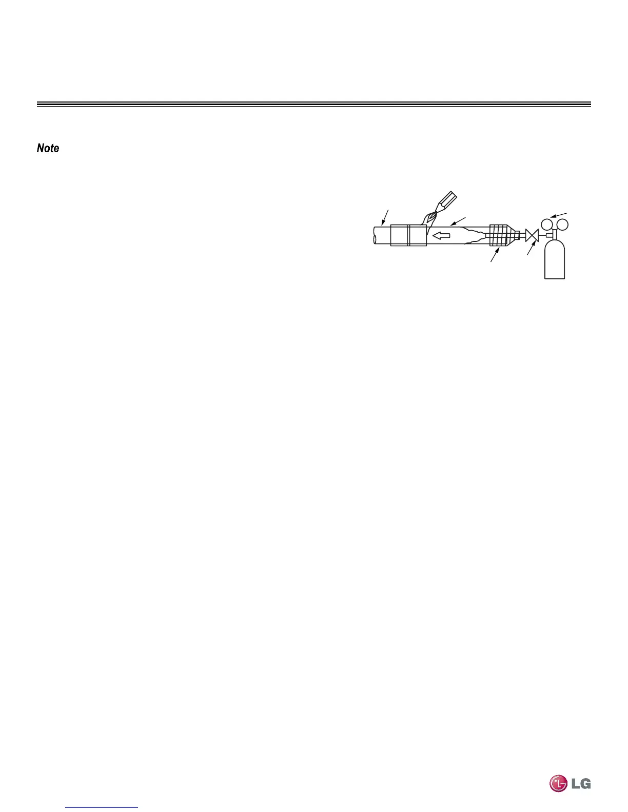
Installation of Refrigerant Piping / Brazing Practices
Pressure-reducing
Valve
Valve
Taping
Nitrogen
Pipe to
be brazed
Refrigerant
Piping
Figure 40: Refrigerant Pipe Brazing.
It is imperative to keep the piping system free of contaminants and debris such as copper burrs, slag, or carbon dust during installation.
Refrigerant Piping System Insulation
All refrigerant piping including Y-branch and Header connections, field-provided isolation ball valves, service valves, and elbows shall be
completely insulated using closed cell pipe insulation. The liquid and vapor lines must be insulated separately.
To prevent heat loss/heat gain through the refrigerant piping, all refrigerant piping including liquid lines and vapor lines shall be insulated
separately. Insulation shall be a minimum 1/2″ thick, and thickness may need to be increased based on ambient conditions and local codes.
All insulation joints shall be glued with no air gaps. Insulation material shall fit snugly against the refrigeration pipe with no air space between
it and the pipe. Insulation passing through pipe hangers, inside conduit, and/or sleeves must not be compressed. Protect insulation inside
hangers and supports with a second layer. All pipe insulation exposed to the sun and outdoor elements shall be properly protected with PVC,
aluminum vapor barrier, or alternatively placed in a weather-resistant enclosure such as a pipe rack with a top cover; and meet local codes.
The design engineer should perform calculations to determine if the factory-supplied insulation jackets are sufficient to meet local codes and
avoid sweating. Add additional insulation if necessary. Mark all pipes at the point where the insulation jacket ends. Remove the jacket. Install
field provided insulation on the run-out and main truck pipes first. Peel the adhesive glue protector slip from the insulation jacked and install
the clam-shell jacket over the fitting.

 Loading...