Operation
83
.
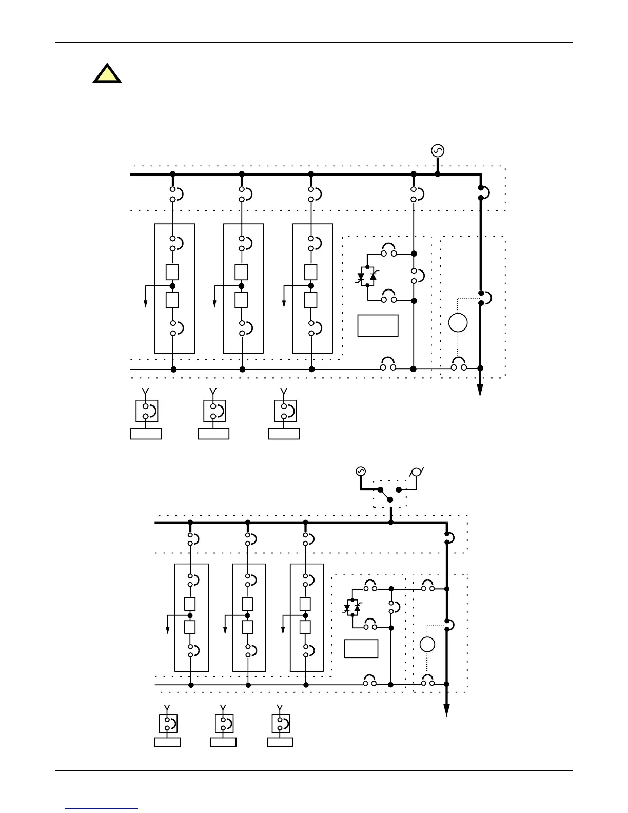
Figure 62 Load on maintenance bypass, two breakers
Figure 63 Load on maintenance bypass, three breakers
!
CAUTION
Instructions for operating the Maintenance Bypass circuit breakers are on the Maintenance
Bypass cabinet. Make sure you understand the proper sequence before operating any circuit
breaker. Operating a Maintenance Bypass circuit breaker out of sequence could cut off power
to the critical load.
I
R
CB2
System
Controls
BFB
Output
SBB
SBS
BFB
I
R
I
R
CB2 CB2
#2UPS
CB1
#1UPS
CB1
#3UPS
CB1
RIB RIB
BIB
RIB
SCCT
SCCT
(can accommodate up to 6 UPS modules)
To Critical Load
Battery
MBD
Battery
MBD
Battery
MBD
SKRU
MIB
MBB
I
R
CB2
System
Controls
BFB
Output
SBB
SBS
BIB
I
R
I
R
CB2 CB2
#2UPS
CB1
#1UPS
CB1
#3UPS
CB1
RIB RIB
RIB
To Critical Load
SCCT
STANDBY GENERATOR
AUTOMATIC
TRANSFER SWITCH
SCCT
(can accommodate up to 6 UPS modules)
Battery
MBD
Battery
MBD
Battery
MBD
SKRU
MBB
MIB
BFB