Page 48 of 192
The LA27 actuator is a powerful actuator designed for a variety of medical applications.
It is developed for both push and pull applications and has a very robust construction
because of the ultrasonic welded plastic housing.
Usage:
• Duty cycle: 2/18; 2 minutes continuous use followed by 18 minutes not in use
• Ambient temperature: +5
o
C to +40
o
C (the actuator must also be at this temp.)
• LA27 is approved according to IEC 60601-1, ANSI/AAMI ES 60601-1 and
CAN/CSA C-22.2 No. 60601-1
• With connection to a static voltage power supply of 33V the lifetime could be
reduced to 5000 cycles (at a constant load of 6000 N).
NOTE: Re. LA27 with 6.000 N specification (274x3xxx1xxx0xZ; Z = A or B with worm shaft*) for OpenBus™.
This combination reduces the self-lock ability because of lower friction from the worm shaft which has a rolled axle. This worm shaft is however
needed because of the OpenBus™ output power.
The self-lock ability may be reduced in cases where the load curve is 6.000 N in both minimum and maximum stroke length.
Recommendations
• LA27 is not meant to have CB6S OBF mounted on the actuator. The CB6S OBF must be mounted separately using a bracket.
• LA27 must have a minimum installation dimension of 320 mm if control box CB6 is to be mounted on the actuator.
• The cable for the LA27 is not part of the actuator therefore it must be ordered separately.
• Piston rod eye: The distance from the centre of the eye, to the end of the actuator.
• Change between push and pull not allowed
• Inspect actuator once a year, for wear and jarring sound.
• We recommend using a safety nut in medical applications
• Do not expose actuators without all cables fitted to water/cleaning.
• No thread on bolt inside back fixture.
Note: For CB6, the current will be cut off when the total current on all channels reaches approx. 5.1 to 5.4 Amp.
This means that when two LA27s, running simultaneously, are connected to a CB6, they will not be able to lift the max. load mentioned under
technical specifications.
6. LA27 (MEDLINE
®
CARELINE
®
HOMELINE
®
)
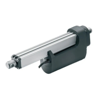
Mount the cable in one of the cable mounting holes
/slots. (If needed both holes/slots can be used)
Replace the Quick Release cover all the way
so that it “clicks” into place.
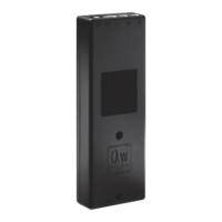
Quick Release gear with spline.
Drawing no.: LA27QR_18
Quick Release gear without spline.
Drawing no.: LA27QR_17
Mounting of the release cable:
Remove the quick release cover, and the
cable mounting holes can be seen.
Ratchet Spline:
*) Z as type “0” does not use the rolled worm shaft. However, type “0” is NOT compatible with the transformer used for OpenBus™ CBs.