User Manual
Lubrigun Pumps 50:1
7.3A-38010-C05
Page 16 of 22
Subject to change
LINCOLN GmbH & Co. KG
∗
Postfach 1263
∗
D-69183 Walldorf
∗
Fax + (49) 6227 33259 ∗ Tel + (49) 6227 330
6. Repair
Repairs must be carried out by skilled, trained
personnel only.
WARNING
Do not attempt to disassemble the
pump while airmotor, pump tube and
other equipment components are
pressurized.
Do not flush or clean pump/pump tube
with flammable fluids.
Hands away from lower part (material
inlet) of the pump while operating or
testing the pump.
• After shutting off the pump, before disassembling
always relieve drive (airmotor), pump tube and other
system components from pressure.
− Disconnect air coupler from the pump, allowing the
compressed air to exhaust completely from the
airmotor.
− Turn valve (Shut-off valve / flow gun) to position
‘open’ at end of the material line and drain the
dispensing material into a collecting can.
Warning: Dispensing material is pressurized.
Always use a container for collecting drained material.
− Shut material valve off when material line is
depressurized and material stops bleeding.
− After pressure relief procedure is completed,
cautiously loosen connector of material supply line at
pump outlet; remove material line (connecting hose)
from pump.
6.1 Tools required
Hex keys and Hex. wrenches with inch-measures are
required. Furthermore pliers, screw drivers and other
standard tools of a workshop are required for the
disassembly of the pump.
6.
2 Disassembly instructions
The disassembly instructions are designated for service
personnel only with special knowledge and experience
of hydraulic and pneumatic equipment.
Attention: Never make any modifications! Use original
spare parts only. See service parts list.
Collect dispensing material. Ensure that all con-
sumables are disposed of safely according to the
regulations of the authorities after repair.
Note: All codes indicated in bold-type bracket ( ) refer to
item numbers listed on service parts dwg. and service
parts list.
Adhere to stated torque specifications on re-assembly:
(21) Valve cover screw
1/2“ hex. hd 10,5-11 Nm
(25) Trip rod packing nut
3/4“ hex. hd. 13,6-20,3 Nm
(57) Hex. socket screw
5/32“ hex. 3,4-4,4 Nm
(71) Hex. socket screw
5/32“ hex. 3,4-4,4 Nm
Maintenance of the Air Valve Mechanism
Greasing of air valve mechanism
Lubricate air valve mechanism located inside of the Air
Valve Casting (4) at least once a year with grease.
Use ~ 45 cm
3
N.L.G.I. No. 1 (light grade) water repellent
grease for lubrication. Replace O-Ring (20).
a) Disconnect air coupler from the pump. Turn valve to
position ‘open’ at end of the material line and drain
the material into a collecting can.
b) After pressure relief procedure is completed, remove
the four Valve Cover Screws (21), Cover (72) and
O-Ring (20) from Air Valve Casting of the airmotor.
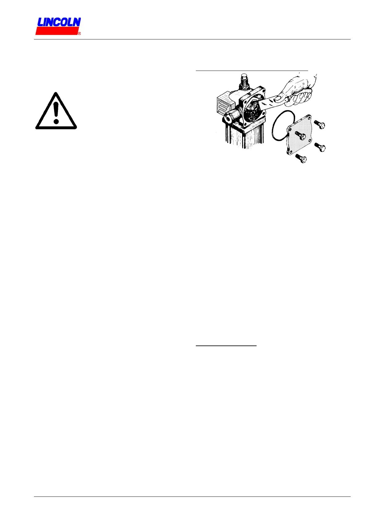
c) Remove old grease. Wear safety glasses! Use air
blow gun to remove any chips or foreign particles.
d) Use spatula, as illustrated, to pack also cavity behind
the Toggle Plate with grease.
e) Check if O-Ring is correctly seated before re-
assembling the Cover.
f) Fasten the four 1/2“ hex. head Screws (21) of the
Cover with torque of 10,5-11 Nm.
Remark: On repair/overhaul and disassembly of the
airmotor head (disassembly of pump and pump parts),
carefully clean parts including the air valve casting
before re-assembly and greasing.
Disassembly of pump.
After pressure relief procedure is performed and pump
is removed for service, clamp pump by a vise at outlet
body.
1. Remove Valve Cap (1) from Air Valve Casting (4);
remove Valve Cap Gasket (3).
2. Remove Trip Rod Pin (2) and Trip Rod Collar (19).
3. Unscrew Tie Rod Nuts (75) from the four Tie
Rods (63).
4. Lift Air Valve Casting (4) manually a little off from Air
Cylinder (13) until Trip Rod is exposed and
cautiously grip (do not damage rod) Trip Rod (16) in
front of the Trip Rod Packing Nut (25); unscrew Trip
Sleeve (5) from end of the Trip Rod (16).
Lubrigun Pumps No. 82050, No. 82054, No. 83513, No. 82050-E575, Ser. J