User Manual
Lubrigun Pumps 50:1
7.3A-38010-C05
Page 7 of 22
Subject to change
LINCOLN GmbH & Co. KG
∗
Postfach 1263
∗
D-69183 Walldorf
∗
Fax + (49) 6227 33259 ∗ Tel + (49) 6227 330
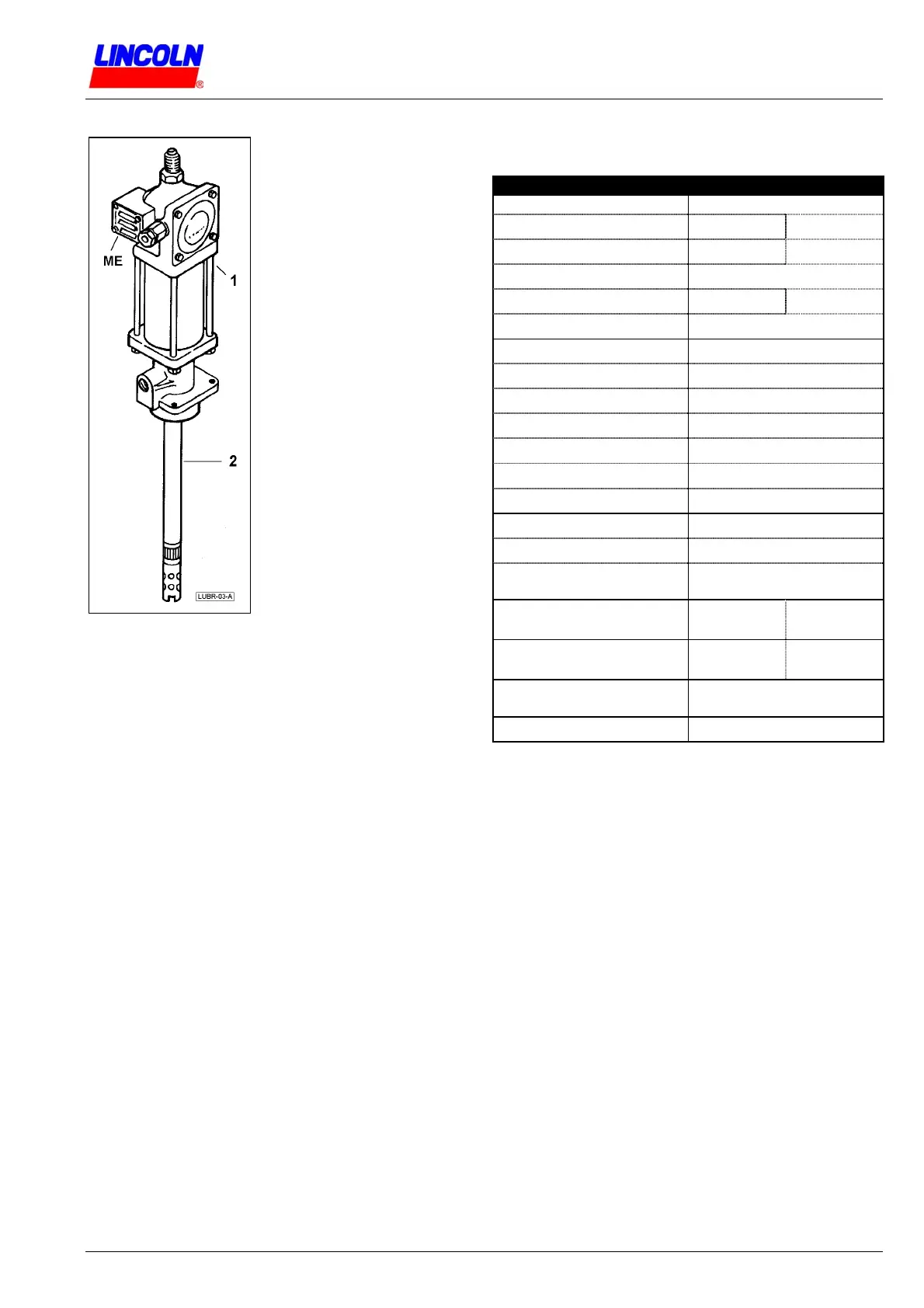
3.2 General Description
Pump Models:
No. 82050, No. 82054,
No. 83513, No. 82050-E575.
Pump models listed above are
of same technical design. The
models differ by length of the
pump tube (2) only.
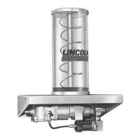
1
Pump drive
(airmotor)
2
Pump tube
(piston pump)
ME
Air exhaust
(muffler)
1 & 2 are one unity.
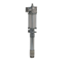
Lubrigun Pump
Lubrigun Pumps 50:1
are air operated, double acting pumps with differential
piston.
The pump discharges the material on “up“ and “down“
stroke to the outlet; material intake on “up“ stroke.
The pump transforms the incoming air pressure in a
50-times higher material delivery pressure.
The pump has a shovel-type foot valve. The shovel
supports the intake of the material to be pumped by
mechanical force; recommended application for
pumping chassis grease.
For pumping fluid and flowable lubricants, this pump
type can be optionally equipped with ball-type Foot
Valve No. 61275-E.
The pump tube is equipped with a precisely fitted piston
for appropriate use which is the pumping of lubricants.
The non-adherence of the designated use, for example
pumping of materials not having lubricating properties
may cause premature wear and damage to the bushing
& plunger assembly of the pump tube.
Accessories
depend on specific requirement. Ask for quotation in
case of requirement.
Air pressure regulator required for pump drive. Use 1/4“
(DN6) FRL-Air service unit (Filter, regulator, gauge,
lubricator) if compressed air is not free from foreign
particles and moisture.
3.3 Technical Data
Technical Data of Lubrigun pump models listed in
section 3.2:
Technical Data of Pump
Pump Dri v e : Airmotor
Stroke length 63,5 mm 2½“
Air cylinder-Ø 63,5 mm 2½“
Air consumption at 7 bar 4,2 l
(N)
/cycle
Air pressure )
1
min. 2,1 bar max. 10 bar
Air inlet ¼“ NPTF female
Pump Differential plunger pump
Pressure ratio i = 50 : 1
Max. output pressure )
2
500 bar at pump outlet
Discharge volume 5,7 cm
3
/cycle
Delivery output Q
g
0,43 l/min at 75 cycles
Max. pump cycles )
3
120 cycles/minute
Material outlet ¼“ NPTF female
Pump tube
Tube length see 3.4 ‘Dimensions’
Wetted part materials
Soft part seals:
Steel, Ms, Cu, PA,
NBR & Polyurethane
(Materials of pump)
Environmental temperature
TMIN
- 34° C
TMAX
+ 93° C
(Material to be pumped)
Operating temperature )
4
TAMIN
(see remark)
TAMAX
+ 60° C
Noise level
at 8 bar air operating pressure
< 85 dB(A)
Weight see 3.4 ‘Dimensions’
Underline: Cycle = “up“ and “down“ stroke of the pump.
Remarks
)
1
For operating pump with lower air pressure
(< 2,1 bar), attach Spring No. 55231 and Screw
No. 12834 to air valve mechanism of the airmotor.
)
2
Max. delivery pressure at 10 bar air pressure.
Limit air pressure not to exceed the max. working
pressure of the pump. When using system components
that are rated at lower working pressure than this pump,
then take pump pressure ratio of 50:1 into account;
reduce and limit air pressure to pump accordingly.
)
3
Do not exceed 75 cycles/min for continuous
operation. The pump cycles which can be achieved at
normal operation may be less than indicated and
depend on the material to be pumped and other
parameters.
Control pressure and pump cycles using an air pressure
regulator (by user). Always use the lowest pressure
required to achieve the desired results. Higher
pressures may cause pump packings to wear
prematurely.
)
4
The temperature of the material to be pumped must
be in a range that allows the material intake by the
pump and shall not restrict the pumpability of the
material.