LTC2983
32
2983fc
For more information www.linear.com/LTC2983
APPLICATIONS INFORMATION
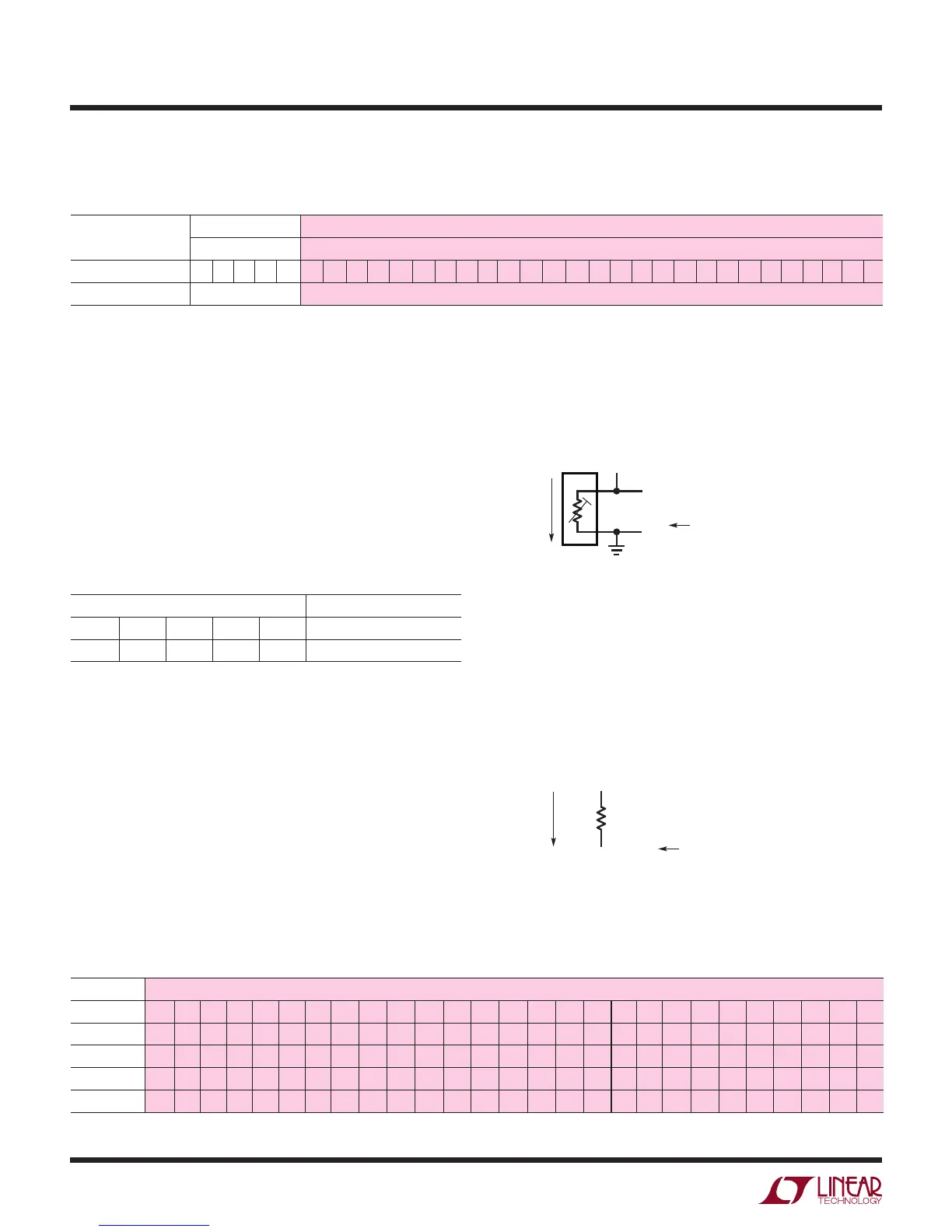
Table 33. Sense Resistor Channel Assignment Word
(1) SENSOR TYPE (2) SENSE RESISTOR VALUE (Ω)
FIGURE 36 FIGURE 40
Measurement Class 31 30 29 28 27 26 25 24 23 22 21 20 19 18 17 16 15 14 13 12 11 10 9 8 7 6 5 4 3 2 1 0
Sense Resistor Type = 29 Sense Resistor Value (17, 10) Up to ≈ 131,072Ω with 1/1024Ω Resolution
Table 34. Sense Resistor Selection
(1) SENSOR TYPE
B31 B30 B29 B28 B27 SENSOR TYPE
1 1 1 0 1 Sense Resistor
Table 35. Example Sense Resistor Values
(2) SENSE RESISTOR VALUE (Ω)
B26 B25 B24 B23 B22 B21 B20 B19 B18 B17 B16 B15 B14 B13 B12 B11 B10 B9 B8 B7 B6 B5 B4 B3 B2 B1 B0
Example R 2
16
2
15
2
14
2
13
2
12
2
11
2
10
2
9
2
8
2
7
2
6
2
5
2
4
2
3
2
2
2
1
2
0
2
–1
2
–2
2
–3
2
–4
2
–5
2
–6
2
–7
2
–8
2
–9
2
–10
10,000.2Ω 0 0 0 1 0 0 1 1 1 0 0 0 1 0 0 0 0 0 0 1 1 0 0 1 1 0 1
99.99521kΩ 1 1 0 0 0 0 1 1 0 1
0 0 1 1 0 1 1 0 0 1 1 0 1 0 1 1 1
1.0023kΩ 0 0 0 0 0 0 0 1 1 1 1 1 0 1 0 1 0 0 1 0 0 1 1 0 0 1 1
Sense Resistor
can be tied directly to 2-lead RTD elements. The disad-
vantages of this topology are errors due to parasitic lead
resistance. If sharing is not selected (1 R
SENSE
per RTD),
then CH
RTD
should be grounded. The ground connection
should be removed if sharing is enabled (1 R
SENSE
for
multiple RTDs).
(2) Sense Resistor Value
The last field in the channel assignment word (B26 to B0)
sets the value of the sense resistor within the range 0 to
131,072Ω with 1/1024Ω precision (see Table 35). The top
17 bits (B26 to B10) create the integer and bits B9 to B0
create the fraction of the sense resistor value.
Example: 2-Wire RTD
The simplest RTD configuration is the 2-wire configura-
tion, 2-wire RTDs follow the general convention shown in
Figure 7. They require only two connections per RTD and
Sense resistor channel assignments follow the general
convention shown in Figure 8. The sense resistor is tied
between CH
RSENSE
and CH
RSENSE-1
, where CH
RSENSE
is
tied to the 2nd terminal of the RTD. Channel assignment
data (see Table 33) is mapped into a memory location
corresponding to CH
RSENSE
.
Figure 7. 2-Wire RTD Channel Assignment Convention
Figure 8. Sense Resistor Channel Assignment Convention for
2-Wire RTDs
2983 F07
OPTIONAL GND, REMOVE FOR R
SENSE
SHARING
2ND TERMINAL TIES TO SENSE RESISTOR (CH
RSENSE
)
2
1
CH
RTD-1
CH
RTD
EXCITATION
CURRENT
FLOW
= CH
RTD
(2≤ RTD ≤ 20)
CHANNEL
ASSIGNMENT
2983 F08
CH
RSENSE-1
CH
RSENSE
R
SENSE
EXCITATION
CURRENT
FLOW
= CH
RSENSE
(2≤ RSENSE ≤ 20)
CHANNEL
ASSIGNMENT
Channel Assignment
For each sense resistor tied to the LTC2983, a 32-bit
channel assignment word is programmed into a memory
location corresponding to the channel the sensor is tied
to (see Table 33). This word includes (1) sense resistor
selection and (2) sense resistor value.
(1) Sensor Type
The sense resistor is selected by setting the first 5 input
bits, B31 to B27, to 11101 (see Table 34).