LTC2983
33
2983fc
For more information www.linear.com/LTC2983
APPLICATIONS INFORMATION
Example: 2-Wire RTDs with Shared R
SENSE
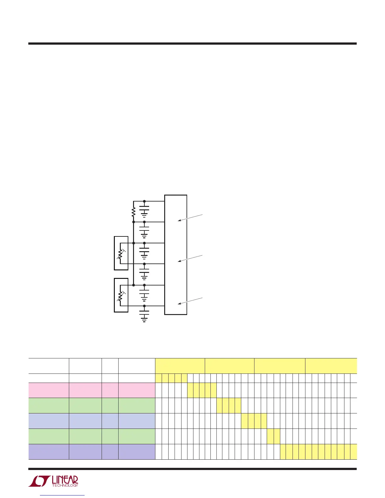
Figure 9 shows a typical temperature measurement system
using multiple 2-wire RTDs. In this example, a PT-1000
RTD ties to CH17 and CH18 and an NI-120 RTD ties to
CH19 and CH20. Using this configuration, the LTC2983 can
digitize up to nine 2-wire RTDs with a single sense resistor.
RTD #1 sensor type and configuration data are as-
signed to CH
18
. 32 bits of binary configuration data are
mapped directly into memory locations 0x244 to 0x247
(see Table 36). RTD #2 sensor type and configuration data
are assigned to CH
20
. 32-bits of binary configuration data
are mapped directly into memory locations 0x24C to 0x24F
Table 36. Channel Assignment Data for 2-Wire RTD #1 (PT-1000, R
SENSE
on CH
16
, 2-Wire, Shared R
SENSE
, 10µA Excitation Current,
α = 0.003916 Curve)
CONFIGURATION
FIELD
DESCRIPTION # BITS BINARY DATA MEMORY
ADDRESS 0x244
MEMORY
ADDRESS 0x245
MEMORY
ADDRESS 0x246
MEMORY
ADDRESS 0x247
(1) RTD TYPE PT-1000 5 01111 0 1 1 1 1
(2) Sense Resistor
Channel Pointer
CH
16
5 10000 1 0 0 0 0
(3) Sensor
Configuration
2-Wire with
Shared R
SENSE
4 0001 0 0 0 1
(4) Excitation
Current
10µA 4 0010 0 0 1 0
(5) Curve Japanese,
α = 0.003916
2 10 1 0
(6) Custom RTD
Data Pointer
Not Custom 12 000000000000 0 0 0 0 0 0 0 0 0 0 0 0
(see Table 37). The sense resistor is assigned to CH
16
.
The user-programmable value of this resistor is 5001.5Ω.
32bits of binary configuration data are mapped directly
into memory locations 0x23C to 0x23F (see Table 38).
A conversion is initiated on CH
18
by writing 10010010 into
memory location 0x000. Once the conversion is complete,
the INTERRUPT pin goes HIGH and memory location
0x000 becomes 01010010. The resulting temperature in
°C can be read from memory locations 0x054 to 0x057
(corresponding to CH
18
). A conversion can be initiated
and read from CH
20
in a similar fashion.
Figure 9. Shared 2-Wire RTD Example
R
SENSE
5001.5Ω
0.01µF
2983 F09
0.01µF
SENSE RESISTOR ASSIGNED TO CH
16
(CH
RSENSE=16
)
RTD #1 ASSIGNED TO CH
18
(CH
RTD=18
)
RTD #2 ASSIGNED TO CH
20
(CH
RTD=20
)
CH
20
CH
19
CH
16
CH
15
CHANNEL ASSIGNMENT
MEMORY LOCATIONS 0x23C TO 0x23F
CHANNEL ASSIGNMENT
MEMORY LOCATIONS 0x244 TO 0x247
RESULT MEMORY LOCATIONS 0x054 TO 0x057
CHANNEL ASSIGNMENT
MEMORY LOCATIONS 0x24C TO 0x24F
RESULT MEMORY LOCATIONS 0x05C TO 0x05F
0.01µF
0.01µF
CH
17
CH
18
0.01µF
0.01µF
2-WIRE PT-1000
2-WIRE NI-120
2
1
2
1