LTC2983
35
2983fc
For more information www.linear.com/LTC2983
Table 39. Channel Assignment Data for 3-Wire RTD (PT-200, R
SENSE
on CH
7
, 3-Wire, 50µA Excitation Current, α = 0.003911 Curve)
CONFIGURATION
FIELD
DESCRIPTION # BITS BINARY DATA MEMORY
ADDRESS 0x220
MEMORY
ADDRESS 0x221
MEMORY
ADDRESS 0x222
MEMORY
ADDRESS 0x223
(1) RTD TYPE PT-200 5 01101 0 1 1 0 1
(2) Sense
Resistor Channel
Pointer
CH
7
5 00111 0 0 1 1 1
(3) Sensor
Configuration
3-Wire 4 0100 0 1 0 0
(4) Excitation
Current
50µA 4 0100 0 1 0 0
(5) Curve American,
α = 0.003911
2 01 0 1
(6) Custom RTD
Data Pointer
Not Custom 12 000000000000 0 0 0 0 0 0 0 0 0 0 0 0
Table 40. Channel Assignment Data for Sense Resistor (Value = 12150.39Ω)
CONFIGURATION
FIELD
DESCRIPTION # BITS BINARY DATA MEMORY
ADDRESS 0x218
MEMORY
ADDRESS 0x219
MEMORY
ADDRESS 0x21A
MEMORY
ADDRESS 0x21B
(1) Sensor Type Sense Resistor 5 11101 1 1 1 0 1
(2) Sense Resistor
Value
12150.39Ω 27 000101111011101100110001111 0 0 0 1 0 1 1 1 1 0 1 1 1 0 1 1 0 0 1 1 0 0 0 1 1 1 0
APPLICATIONS INFORMATION
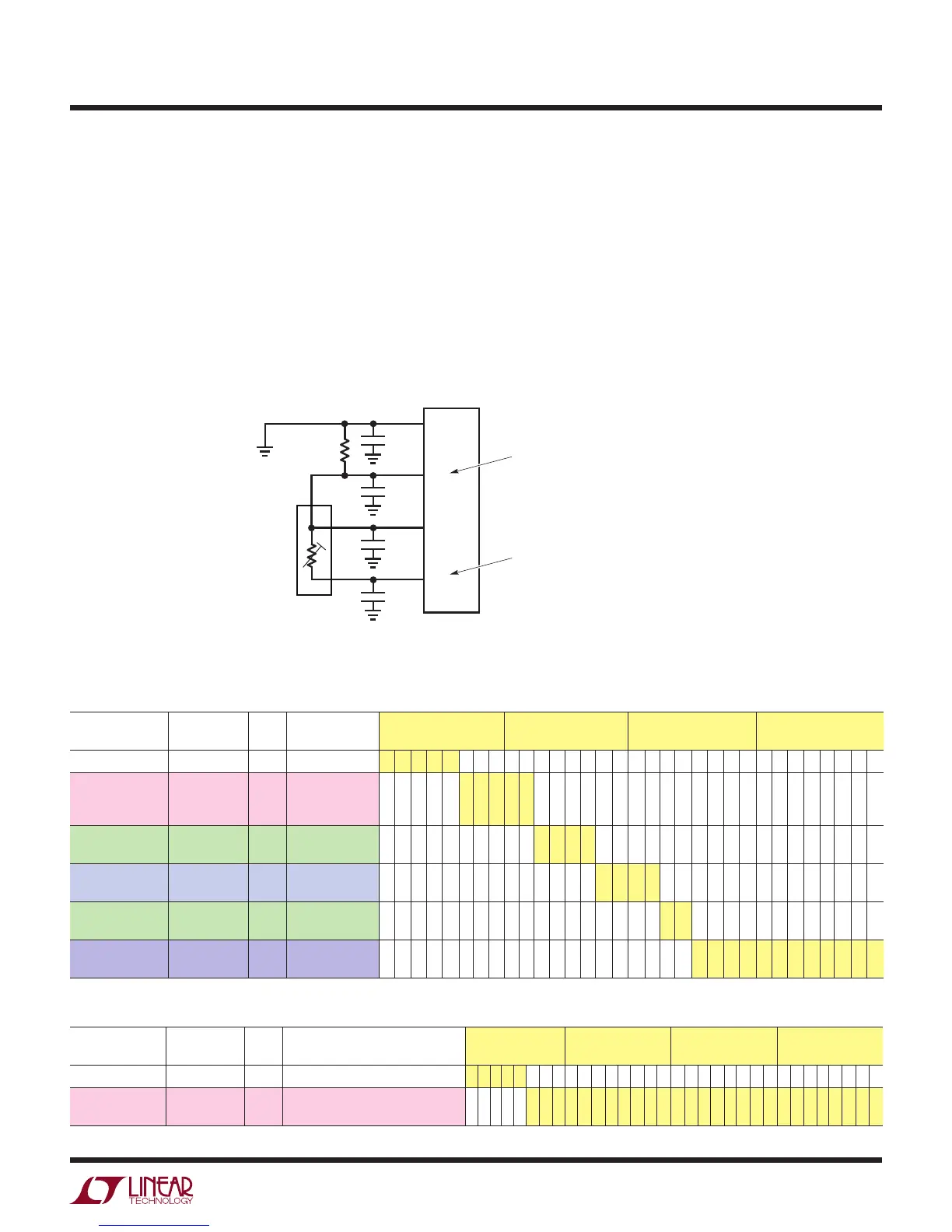
Figure 12 shows a typical temperature measurement sys-
tem using a 3-wire RTD. In this example, a 3-wire RTD’s
terminals tie to CH
9
, CH
8
, and CH
7
. The sense resistor
ties to CH
7
and CH
6
. The sense resistor and RTD connect
together at CH
7
.
The 3-wire RTD reduces the errors associated with para-
sitic lead resistance by applying excitation current to each
RTD input. This first order cancellation removes matched
lead resistance errors. This cancellation does not remove
errors due to thermocouple effects or mismatched lead
resistances. The RTD sensor type and configuration data
are assigned to CH
9
. 32 bits of binary configuration data
are mapped directly into memory locations 0x220 to 0x223
(see Table 39). The sense resistor is assigned to CH
7
. The
user-programmable value of this resistor is 12150.39Ω.
32 bits of binary configuration data are mapped directly
into memory locations 0x218 to 0x21B (see Table 40).
Figure 12. 3-Wire RTD Example
R
SENSE
12,150.39Ω
0.01µF
2983 F12
0.01µF
R
SENSE
ASSIGNED TO CH
7
(CH
SENSE=7
)
3-WIRE RTD ASSIGNED TO CH
9
(CH
RTD=9
)
CH
7
CH
6
CHANNEL ASSIGNMENT
MEMORY LOCATIONS 0x218 TO 0x21B
CHANNEL ASSIGNMENT
MEMORY LOCATIONS 0x220 TO 0x223
RESULT MEMORY LOCATIONS 0x030 TO 0x033
0.01µF
0.01µF
CH
8
CH
9
3-WIRE PT-200
2
3
1