LTC2983
36
2983fc
For more information www.linear.com/LTC2983
APPLICATIONS INFORMATION
A conversion is initiated on CH
9
by writing 10001001 into
memory location 0x000 . Once the conversion is complete,
the INTERRUPT pin goes HIGH and memory location
0x000 becomes 01001001. The resulting temperature in
°C can be read from memory locations 0x030 to 0x033
(corresponding to CH
9
).
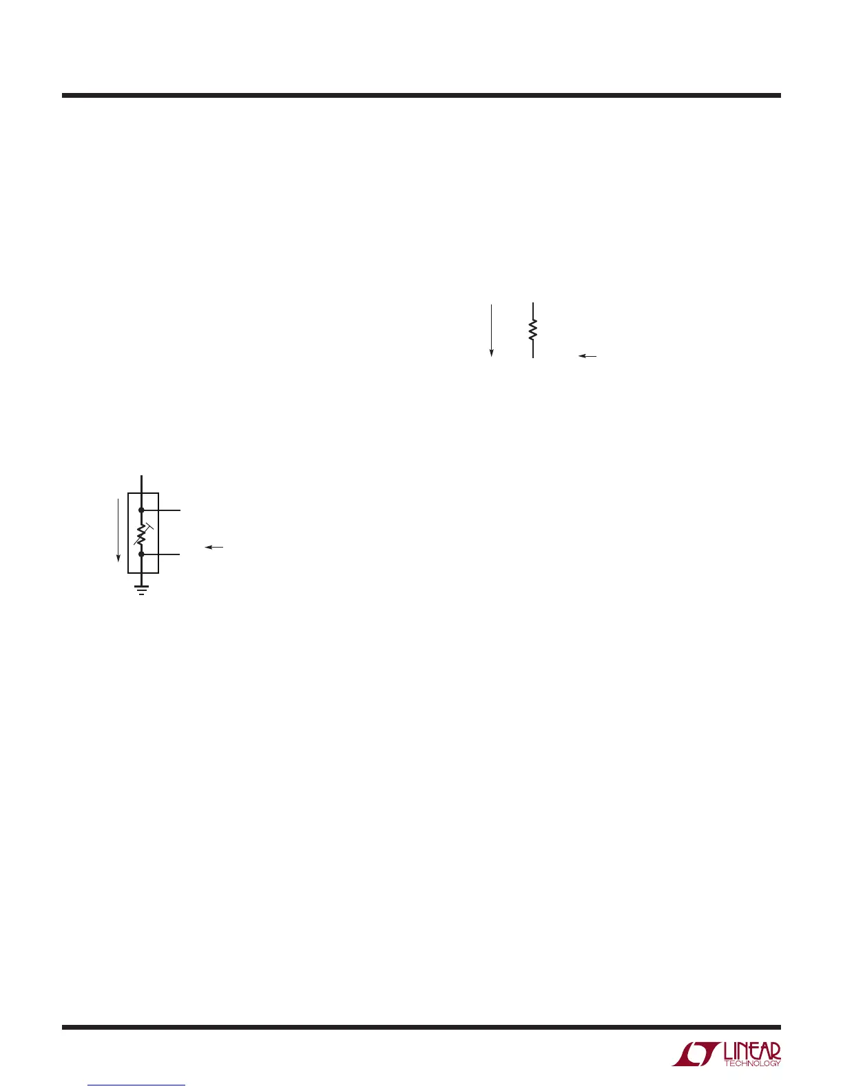
Example: Standard 4-Wire RTD (No Rotation or R
SENSE
Sharing)
Standard 4-wire RTD channel assignments follow the
general convention shown in Figure 13. Terminal 1 is
tied to ground, terminals 2 and 3 (Kelvin sensed signal)
tie to CH
RTD
and CH
RTD-1
, and the 4th terminal ties to the
sense resistor. Channel assignment data (see Table 25)
is mapped to memory locations corresponding to CH
RTD
.
Sense resistor channel assignments follow the general
convention shown in Figure 14. The sense resistor is tied
between CH
RSENSE
and CH
SENSE-1
, where CH
RSENSE
is
tied to the 4th terminal of the RTD. Channel assignment
data (see Table 33) is mapped into a memory location
corresponding to CH
RSENSE
.
Figure 13. 4-Wire RTD Channel Assignment Convention
Figure 14. Sense Resistor Channel Assignment Convention for
4-Wire RTDs
2983 F13
3
4
1
2
CH
RTD-1
CH
RTD
CH
RSENSE
4TH TERMINAL TIES TO SENSE RESISTOR (CH
RSENSE
)
EXCITATION
CURRENT
FLOW
= CH
RTD
(2≤ RTD ≤ 20)
CHANNEL
ASSIGNMENT
2983 F14
CH
RSENSE-1
CH
RSENSE
R
SENSE
EXCITATION
CURRENT
FLOW
= CH
RSENSE
(2≤ RSENSE ≤ 20)
CHANNEL
ASSIGNMENT