LTC2983
37
2983fc
For more information www.linear.com/LTC2983
APPLICATIONS INFORMATION
Table 41. Channel Assignment Data for 4-Wire RTD (PT-1000, R
SENSE
on CH
11
, Standard 4-Wire, 25µA Excitation Current,
α = 0.00385 Curve)
CONFIGURATION
FIELD
DESCRIPTION # BITS BINARY DATA MEMORY
ADDRESS 0x230
MEMORY
ADDRESS 0x231
MEMORY
ADDRESS 0x232
MEMORY
ADDRESS 0x233
(1) RTD TYPE PT-1000 5 01111 0 1 1 1 1
(2) Sense
Resistor Channel
Pointer
CH
11
5 01011 0 1 0 1 1
(3) Sensor
Configuration
4-Wire,
No Rotate,
No Share
4 1000 1 0 0 0
(4) Excitation
Current
25µA 4 0011 0 0 1 1
(5) Curve European,
α=0.00385
2 00 0 0
(6) Custom RTD
Data Pointer
Not Custom 12 000000000000 0 0 0 0 0 0 0 0 0 0 0 0
Table 42. Channel Assignment Data for Sense Resistor (Value = 5000.2Ω)
CONFIGURATION
FIELD
DESCRIPTION # BITS BINARY DATA MEMORY
ADDRESS 0x228
MEMORY
ADDRESS 0x229
MEMORY
ADDRESS 0x22A
MEMORY
ADDRESS 0x22B
(1) Sensor Type Sense Resistor 5 11101 1 1 1 0 1
(2) Sense
Resistor Value
5000.2Ω 27 000010011100010000011001100 0 0 0 0 1 0 0 1 1 1 0 0 0 1 0 0 0 0 0 1 1 0 0 1 1 0 0
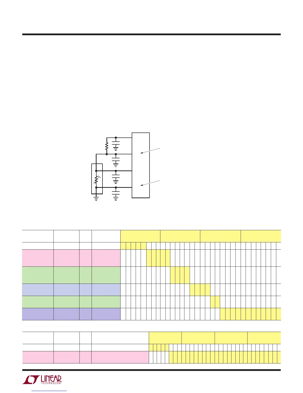
Figure 15 shows a typical temperature measurement
system using a 4-wire RTD. In this example, a 4-wire
RTD’s terminals tie to GND, CH
13
, CH
12
, and CH
11
. The
sense resistor ties to CH
11
and CH
10
. The sense resis-
tor and RTD share a common connection at CH
11
. The
RTD sensor type and configuration data are assigned to
CH
13
. 32 bits of binary configuration data are mapped
directly into memory locations 0x230 to 0x233 (see
Table 41). The sense resistor is assigned to CH
11
. The
user programmable value of this resistor is 5000.2Ω.
32 bits of binary configuration data are mapped directly
into memory locations 0x228 to 0x22B (see Table 42).
A conversion is initiated on CH
13
by writing 10001101
into the data byte at memory location 0x000. Once the
conversion is complete, the INTERRUPT pin goes HIGH
and memory location 0x000 becomes 01001101. The
resulting temperature in °C can be read from memory
locations 0x040 to 0x043 (corresponding to CH
13
).
Figure 15. Standard 4-Wire RTD Example
R
SENSE
5000.2Ω
0.01µF
2983 F15
0.01µF
SENSE RESISTOR ASSIGNED TO CH
11
(CH
SENSE=11
)
RTD ASSIGNED TO CH
13
(CH
RTD=13
)
CH
11
CH
10
CHANNEL ASSIGNMENT
MEMORY LOCATIONS 0x228 TO 0x22B
CHANNEL ASSIGNMENT
MEMORY LOCATIONS 0x230 TO 0x233
RESULT MEMORY LOCATIONS 0x040 TO 0x043
0.01µF
0.01µF
CH
12
CH
13
4-WIRE PT-1000
3
4
2
1