LTC2983
38
2983fc
For more information www.linear.com/LTC2983
APPLICATIONS INFORMATION
Example: 4-Wire RTD with Rotation
One method to improve the accuracy of an RTD over the
standard 4-wire implementation is by rotating the excita-
tion current source. Parasitic thermocouple effects are
automatically removed through autorotation. In order to
perform autorotation, the 1st terminal of the RTD ties to
CH
RTD+1
instead of GND, as in the standard case. This
allows the LTC2983 to automatically change the direc-
tion of the current source without the need for additional
external components.
4-wire RTD with rotation channel assignments follow
the general convention shown in Figure 16. Terminal 1 is
tied to CH
RTD+1
, terminals 2 and 3 (Kelvin sensed signal)
tie to CH
RTD
and CH
RTD-1
, and the 4
th
terminal ties to the
sense resistor. Channel assignment data (see Table25) is
mapped to memory locations corresponding to CH
RTD
.
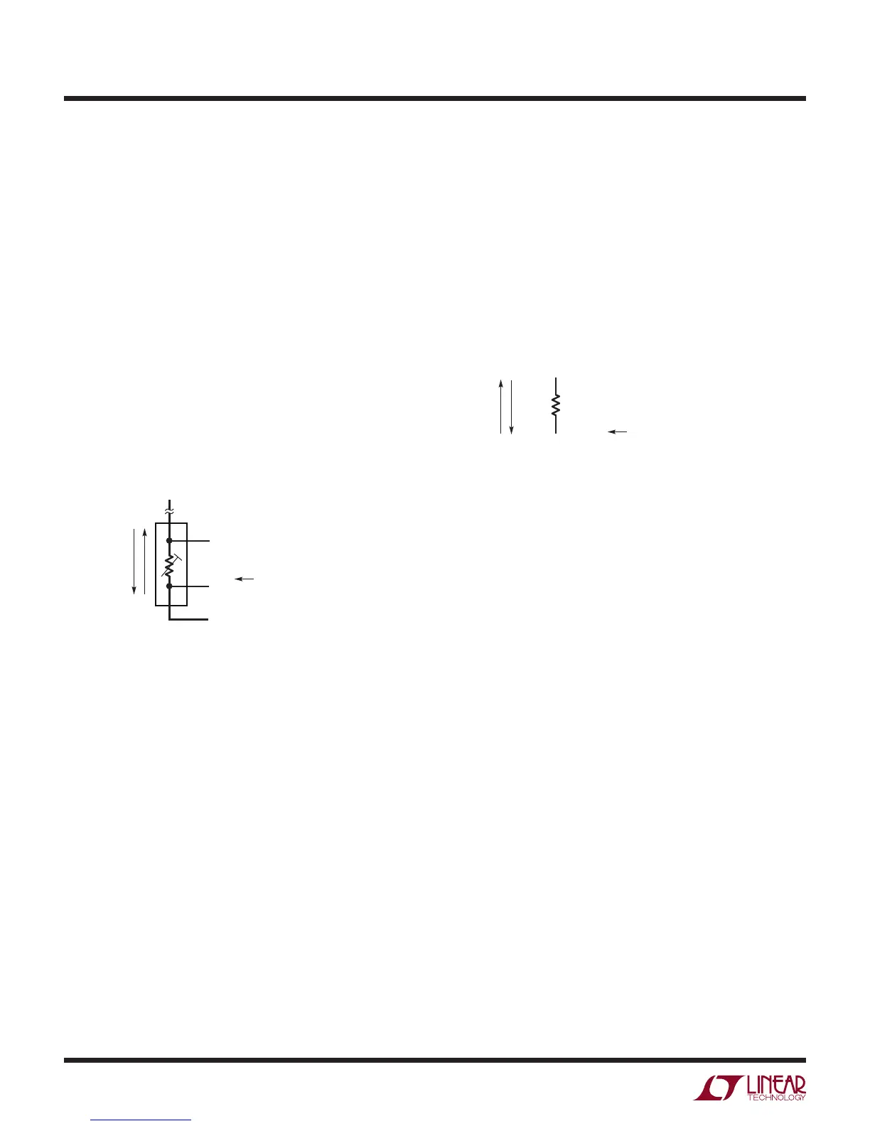
Sense resistor channel assignments follow the general
convention shown in Figure 17. The sense resistor is tied
between CH
RSENSE
and CH
RSENSE-1
, where CH
RSENSE
is
tied to the 4
th
terminal of the RTD. Channel assignment
data is mapped into a memory location corresponding to
CH
RSENSE
.
Figure 16. 4-Wire RTD Channel Assignment Convention
Figure 17. Sense Resistor Channel Assignment Convention for
4-Wire RTDs with Rotation
2983 F17
CH
RSENSE-1
CH
RSENSE
R
SENSE
EXCITATION
CURRENT
FLOW
= CH
RSENSE
(2≤ RSENSE ≤ 20)
CHANNEL
ASSIGNMENT
2983 F16
3
4
1
2
CH
RTD–1
CH
RTD
CH
RTD+1
EXCITATION
CURRENT
FLOW
= CH
RTD
(2≤ RTD ≤ 19)
CH
RSENSE
4
TH
TERMINAL TIES TO SENSE RESISTOR
CHANNEL
ASSIGNMENT