LTC2983
40
2983fc
For more information www.linear.com/LTC2983
APPLICATIONS INFORMATION
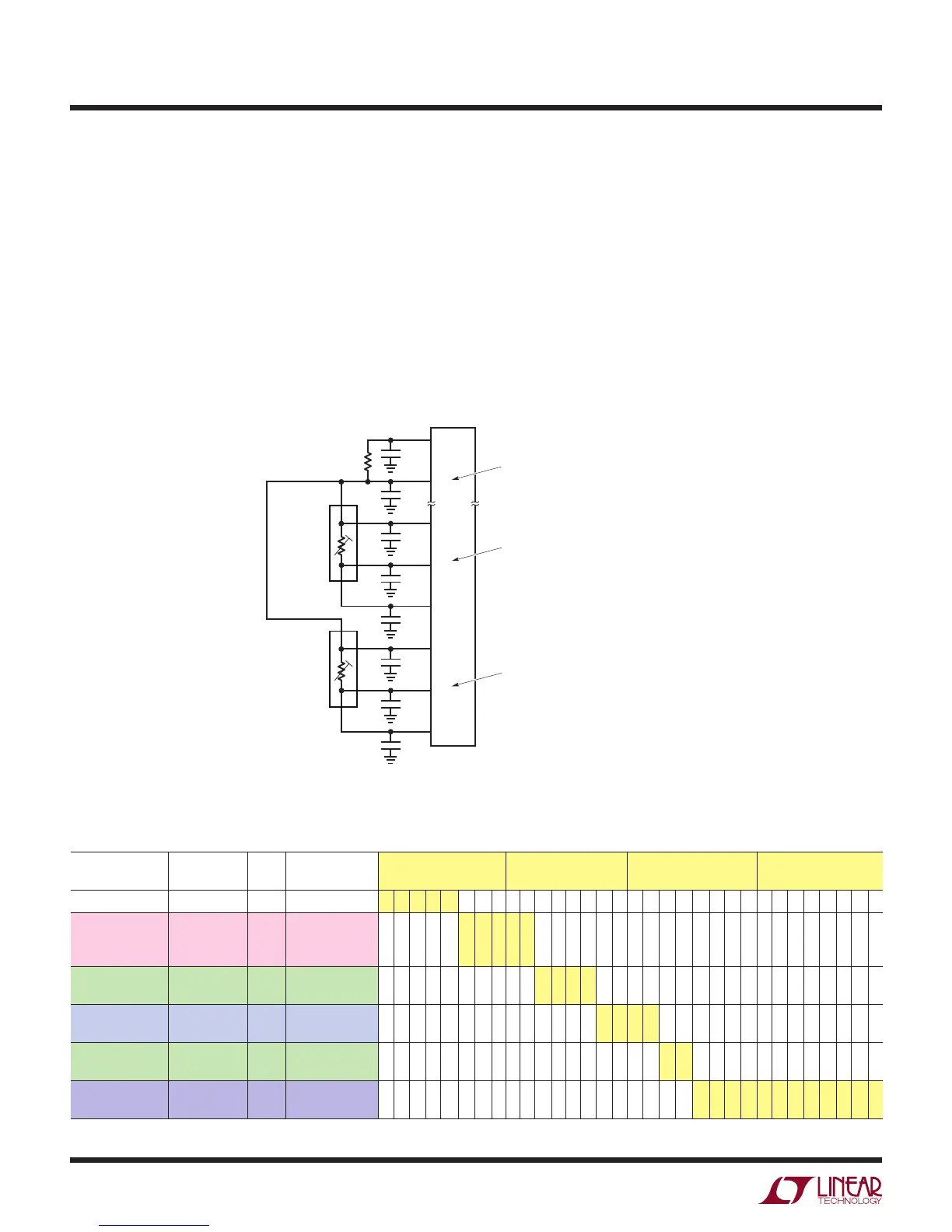
Example: Multiple 4-Wire RTDs with Shared R
SENSE
Figure 19 shows a typical temperature measurement
system using two 4-wire RTDs with a shared R
SENSE
.
The LTC2983 can support up to six 4-wire RTDs with
a single sense resistor. In this example, the first 4-wire
RTD’s terminals tie to CH
17
, CH
16
, CH
15
, and CH
6
and
the 2nd ties to CH
20
, CH
19
, CH
18
, and CH
6
. The sense
resistor ties to CH
5
and CH
6
. The sense resistor and both
RTDs connect together at CH6. This channel assignment
convention is identical to that of the rotating RTD. This
Table 45. Channel Assignment Data for 4-Wire RTD #1 (PT-100, R
SENSE
on CH
6
, 4-Wire, Shared R
SENSE
, Rotated 100µA Excitation
Current, α = 0.003926 Curve)
CONFIGURATION
FIELD
DESCRIPTION # BITS BINARY DATA MEMORY
ADDRESS 0x23C
MEMORY
ADDRESS 0x23D
MEMORY
ADDRESS 0x23E
MEMORY
ADDRESS 0x23F
(1) RTD TYPE PT-100 5 01100 0 1 1 0 0
(2) Sense
Resistor Channel
Pointer
CH
6
5 00110 0 0 1 1 0
(3) Sensor
Configuration
4-Wire
Rotated
4 1010 1 0 1 0
(4) Excitation
Current
100µA 4 0101 0 1 0 1
(5) Curve ITS-90,
α=0.003926
2 11 1 1
(6) Custom RTD
Data Pointer
Not Custom 12 000000000000 0 0 0 0 0 0 0 0 0 0 0 0
topology supports both rotated and non-rotated RTD
excitations. Channel assignment data for each sensor is
shown in Tables 45 to 47.
A conversion is initiated on CH
16
by writing 10010000 into
memory location 0x000. Once the conversion is complete,
the INTERRUPT pin goes HIGH and memory location
0x000 becomes 01010000. The resulting temperature in
°C can be read from memory locations 0x04C to 0x04F
(corresponding to CH
16
). A conversion can be initiated
and read from CH
19
in a similar fashion.
Figure 19. Shared R
SENSE
4-Wire RTD Example
R
SENSE
10k
0.01µF
2983 F19
0.01µF
SENSE RESISTOR ASSIGNED TO CH
6
(CH
SENSE=6
)
RTD #1 ASSIGNED TO CH
16
(CH
RTD=16
)
CH
6
CH
5
CHANNEL ASSIGNMENT
MEMORY LOCATIONS 0x214 TO 0x217
CHANNEL ASSIGNMENT
MEMORY LOCATIONS 0x23C TO 0x23F
RESULT MEMORY LOCATIONS 0x04C TO 0x04F
0.01µF
CH
15
CH
16
CH
17
CH
18
CH
19
CH
20
RTD #2 ASSIGNED TO CH
19
(CH
RTD=19
)
CHANNEL ASSIGNMENT
MEMORY LOCATIONS 0x248 TO 0x24B
RESULT MEMORY LOCATIONS 0x058 TO 0x05B
4-WIRE PT-100
0.01µF
0.01µF
3
4
2
1
0.01µF
4-WIRE PT-500
0.01µF
0.01µF
3
4
2
1