LTC2983
41
2983fc
For more information www.linear.com/LTC2983
APPLICATIONS INFORMATION
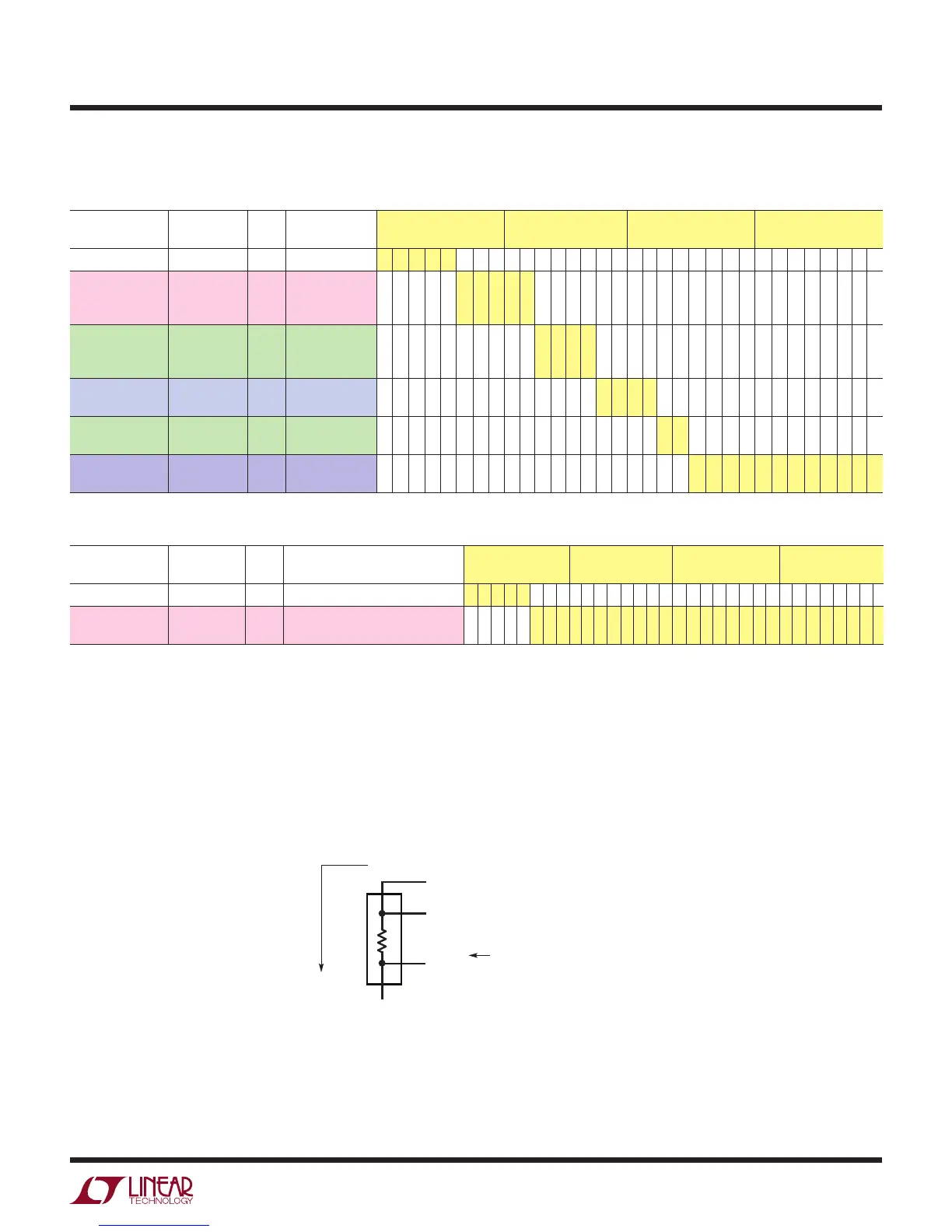
Table 46. Channel Assignment Data for 4-Wire RTD #2 (PT-500, R
SENSE
on CH
6
, 4-Wire, Rotated 50µA Excitation Current,
α = 0.003911 Curve)
CONFIGURATION
FIELD
DESCRIPTION # BITS BINARY DATA MEMORY
ADDRESS 0x248
MEMORY
ADDRESS 0x249
MEMORY
ADDRESS 0x24A
MEMORY
ADDRESS 0x24B
(1) RTD TYPE PT-500 5 01110 0 1 1 1 0
(2) Sense
Resistor Channel
Pointer
CH
6
5 00110 0 0 1 1 0
(3) Sensor
Configuration
4-Wire
Shared,
No Rotation
4 1001 1 0 0 1
(4) Excitation
Current
50µA 4 0100 0 1 0 0
(5) Curve American,
α=0.003911
2 01 0 1
(6) Custom RTD
Data Pointer
Not Custom 12 000000000000 0 0 0 0 0 0 0 0 0 0 0 0
Table 47. Channel Assignment Data for Sense Resistor (Value = 10.000kΩ)
CONFIGURATION
FIELD
DESCRIPTION # BITS BINARY DATA MEMORY
ADDRESS 0x214
MEMORY
ADDRESS 0x215
MEMORY
ADDRESS 0x216
MEMORY
ADDRESS 0x217
(1) Sensor Type Sense Resistor 5 11101 1 1 1 0 1
(2) Sense
Resistor Value
10.000kΩ 27 000100111000100000000000000 0 0 0 1 0 0 1 1 1 0 0 0 1 0 0 0 0 0 0 0 0 0 0 0 0 0 0
Example: 4-Wire RTD with Kelvin R
SENSE
It is possible to cancel the parasitic lead resistance in
the sense resistors by configuring the 4-wire RTD with
a 4-wire (Kelvin connected) sense resistor. This is useful
when using a PT-10 or PT-50 with a small valued R
SENSE
or when the sense resistor is remotely located or in ap-
plications requiring extreme precision.
The 4-wire RTD channel assignments follow the general
conventions previously defined (Figures 14 and 16) for
a standard 4-wire RTD. The sense resistor follows the
convention shown in Figure 20.
Figure 20. Sense Resistor with Kelvin Connections Channel Assignment Convention
2983 F20
3
4
1
2
CH
RSENSE–1
CH
RSENSE–2
CH
RSENSE
R
SENSE
TIES TO RTD TERMINAL 4
EXCITATION
CURRENT
FLOW
= CH
RSENSE
(3≤ RSENSE ≤ 20)
CHANNEL
ASSIGNMENT