www.linearcorp.com 12 eMerge Essential Installation Manual
To determine standby battery time:
1. Determine the total standby load of the system by adding the maximum and standby current
draw of the devices connected to the panel. For example, if the system consists of the control
panel (200 mA) and one 75 mA reader the total standby load is 275 mA (200 mA+ 75 mA).
2. Divide the total standby load by 1000 to convert it to amps. For example, 275 / 1000 = .275.
3. Divide the amp-hour rating of the battery by the total standby load to determine the standby
time for the system. For example, 7.0 / .275 = 25.5 hours standby time using a 7 AH battery
with a system that consists of the control panel and one 75 mA reader.
Power Fault
If AC power loss is detected, the power supervision module will automatically switch to the
backup battery and activate the fault input. e fault input can be congured via programming to
activate a condition (dialer, etc.). e transaction will be logged in the history of the controller.
Tamper Protection
A tamper switch is mounted inside the enclosure and is pre-wired to the tamper input on the
terminal strip. If the eMerge Essential cover is removed for any reason the tamper switch will
activate, triggering a condition that can be linked to an event action in programming (e.g., send
an e-mail or generate an output).
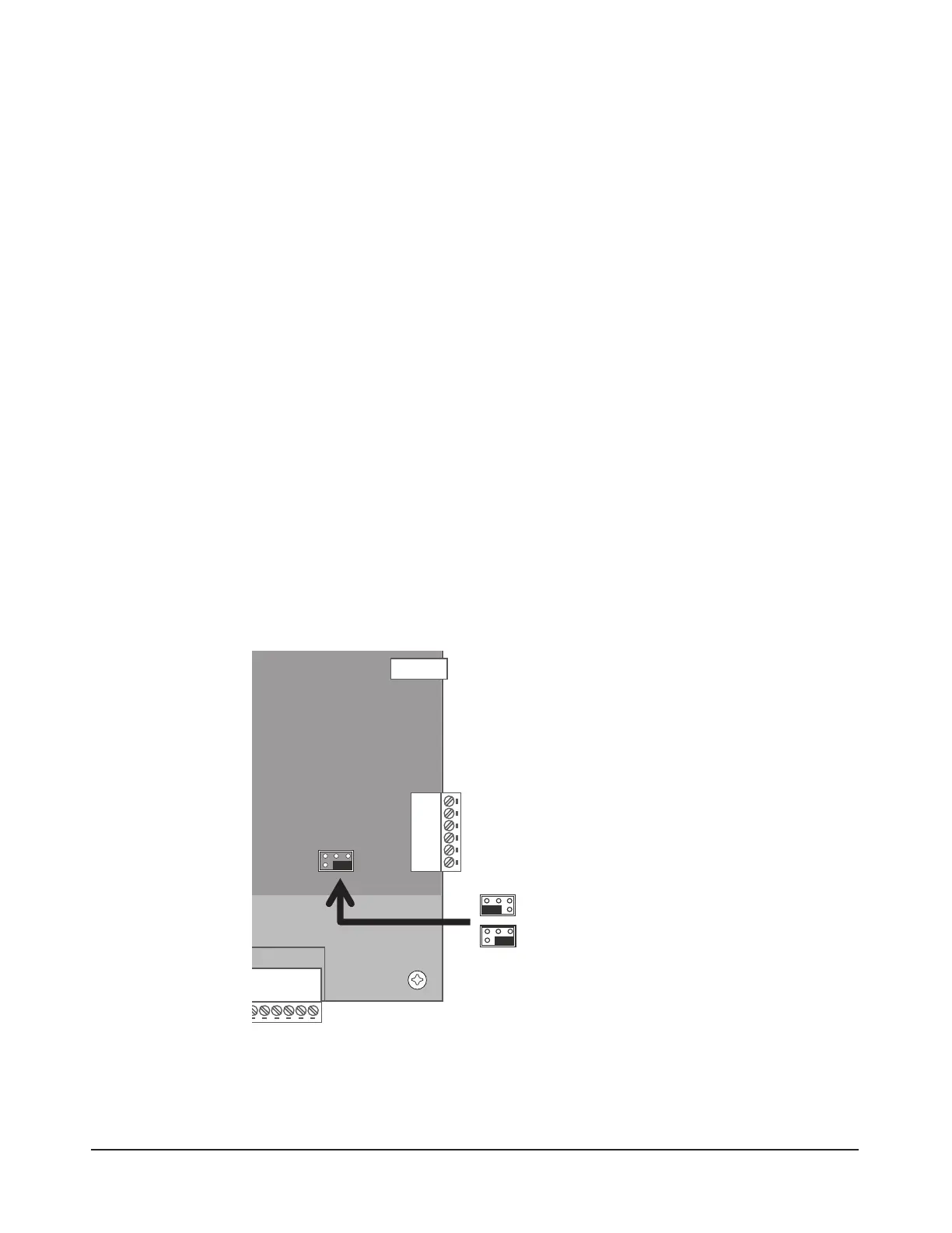
PoE Connection
e eMerge Essential can be powered using Power over Ethernet (PoE), which is a method for
providing power via Ethernet cabling. To place the controller in PoE mode, move the Power
Input Jumper to the left position as illustrated in Figure 4.4.
A Power over Ethernet installation must consist of a high-power 30W PoE injector (P/N POE-
PLUS) and the Liner E3-POE module (P/N 620-100159). Refer to the PoE module’s installa-
tion guide for specic installation information.
PIN 6
PIN 5
PIN 4
PIN 3
PIN 2
PIN 1
EMERGE ESSENTIAL CONTROL PANEL
6-pin terminal block
AUX RELAY 4
AUX RELAY 3
AUX RELAY 2
AUX RELAY 1
AUX INPUT 4
AUX INPUT 3
AUX INPUT 2
AUX INPUT 1
INPUT
GND
INPUT
GND
+12V
LED
Buzzer
D0
D1
GND
NC
C
NO
+12V
LED
Buzzer
D0
D1
GND
INPUT
GND
INPUT
GND
+12V
LED
Buzzer
D0
D1
GND
NC
C
NO
AUX IN 2
GND
AUX IN 1
GND
AUX IN 4
GND
AUX IN 3
GND
NC
C
NO
NC
C
NO
AUX
RLY 4
AUX
RLY 3
NC
C
NO
NC
C
NO
+12V
LED
Buzzer
D0
D1
GND
+12V
LED
Buzzer
D0
D1
GND
INPUT
GND
INPUT
GND
NC
C
NO
+12V
LED
Buzzer
D0
D1
GND
+12V
LED
Buzzer
D0
D1
GND
INPUT
GND
INPUT
GND
NC
C
NO
DOOR 1
DOOR 2
DOOR 3
DOOR 4
AUX
RLY 2
AUX
RLY 1
Enclosure Knockouts
Screw for cover
Enclosure Knockouts
Top Mounting Hole
Top Mounting Hole
JP1
EXTERNAL 12VDC
POE
(Default)
Figure 4.4. Power Input Jumper
Note: The eMerge Es-
sential controller board
consumes 200 mA of cur-
rent at 12VDC (2.4W).
Note: The Linear PoE
module (P/N 620-100159)
must be installed in order
to use a PoE injector (P/N
POE-PLUS).