www.linearcorp.com 6 eMerge Essential Installation Manual
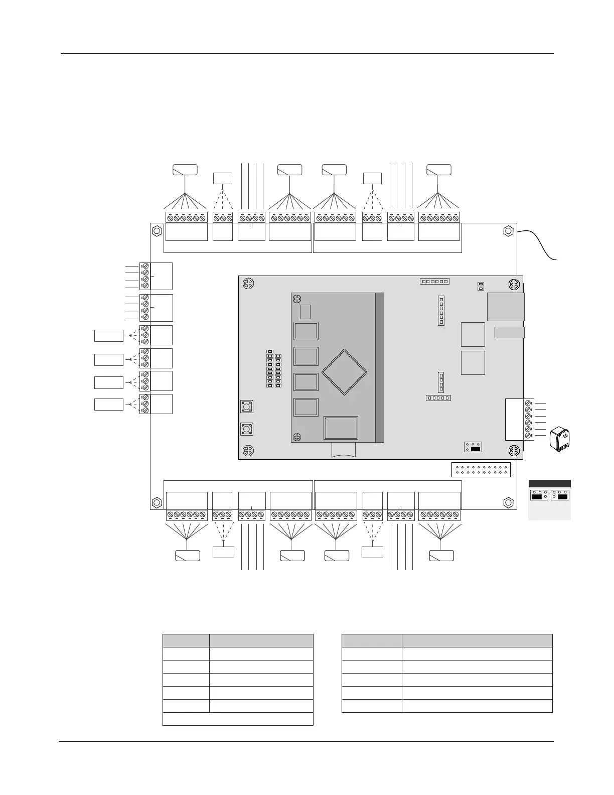
2.0 Control Panel Layout
Control Panel Components
e following illustration shows the eMerge control panel wiring and components.
DOOR 1
LOCK
IN READER 1OUT READER 1
DOOR 1 CONTACTREX 1
DOOR 2
LOCK
IN READER 2OUT READER 2
AUX RELAY 4
AUX RELAY 3
AUX RELAY 2
AUX RELAY 1
AUX INPUT 4
AUX INPUT 3
AUX INPUT 2
AUX INPUT 1
+12VDC / 5A
(100-240 VAC)
TAMPER
DOOR 3
LOCK
IN READER 3
OUT READER 3
REX 3
DOOR 3
CONTACT
REX 4
DOOR 4
CONTACT
DOOR 4
LOCK
IN READER 4
OUT READER 4
+12V
LED
D0
D1
GND
INPUT
GND
INPUT
GND
+12V
LED
D0
D1
GND
NC
C
NO
+12V
LED
D0
D1
GND
INPUT
GND
INPUT
GND
+12V
LED
D0
D1
GND
NC
C
NO
AUX IN 3
GND
AUX IN 4
GND
AUX IN 1
GND
AUX IN 2
GND
NC
C
NO
NC
C
NO
NC
C
NO
NC
C
NO
+12V
LED
D0
D1
GND
+12V
LED
D0
D1
GND
INPUT
GND
INPUT
GND
NC
C
NO
+12V
LED
D0
D1
GND
+12V
LED
Buzzer
D0
D1
GND
INPUT
GND
INPUT
GND
NC
C
NO
DOOR 1DOOR 2
DOOR 3DOOR 4
DOOR 2 CONTACTREX 2
ETHERNET
TMP -
TMP +
FLT -
FLT +
GND
12VDC
PWR FAULT
SD CARD
SLOT
RESET
LED BANK
LAN LED
DL8
DL7
DL6
DL5
DL4
DL3
DL2
DL1
DL17
DL16
DL15
DL14
DL13
DL12
DL11
DL10
DL9
DL19
DL18
JP1
S2
S1
External
+12VDC
POE
(Default)
JP1 - Power Input
EARTH
GROUND
LEAD
Figure 2.1. eMerge Board Layout
Table 2.1: LED Indicators Table 2.2: Default I/O States
LED Condition
DL17 Red On = Power On Bottom Board
DL9 Red On = Power On Middle Board
DL1 Blue On = System is Rebooted
DL1 to DL16 Blue On = System is Booting
DL19, DL 18 Blue Blink = Network Connection
NOTE: Boot up time is approx. 60 secs.
Attribute Default State
Door Status Inputs
Normally Open, Unsupervised, 8 Sec. Held Open Time
REX Inputs Normally Open, Momentary, Unsupervised
Auxiliary Inputs Normally Open, Unsupervised
Door Lock Outputs Not Energized, Single Pulse, 3 Second Unlock Time
Aux Outputs Not Energized, Single Pulse, 3 Seconds On